Download
1 / 22
220 likes | 305 Views
School of Electrical and Computer Engineering. Wireless Telemetry System for Solar Vehicle. Scott Cowan Elliot Hernandez Tung Le April 25, 2011. Project Overview. Source: http://www.ece.gatech.edu/academic/courses/ece4007/10fall/ECE4007L01/ws1/files/sjt_final_presentation.ppt.

E N D
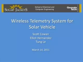
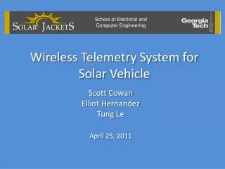
School of Electrical and Computer Engineering Wireless Telemetry System for Solar Vehicle Scott Cowan Elliot Hernandez Tung Le April 25, 2011
Project Overview Source: http://www.ece.gatech.edu/academic/courses/ece4007/10fall/ECE4007L01/ws1/files/sjt_final_presentation.ppt
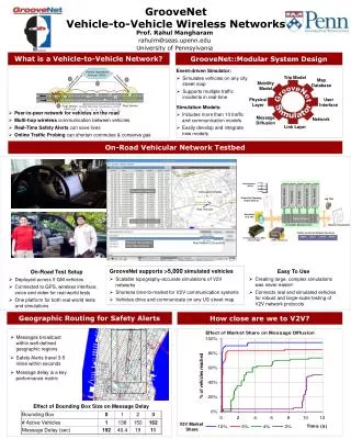
Design Overview Solar Car Current Transmitter Data Storage Chase Car Speed USB USB SBC Temperature SPI DIO Laptop RS-485/RS-232 USB Voltage Battery Mgmt. Motor Ctrl. MPPT HMI GPS
Design Problems & Solutions Problem: Programming C code for TCP/IP protocol for file sync Solution: Switched to C++ to use FTP protocol Problem: Using hardware SPI for the ADC converter Solution: Bit-bang(software based) using the SPI bus
Hardware Problems & Solutions Problem: PCB errors discovered too late to correct Solution: Used wires to bypass incorrect traces; corrected schematics and PCB files for future reference
Outside View of Telemetry Box Comm. Jacks Input Terminals USB Ports
Inside View of Telemetry Box Flash Drive PCB SBC USB Hub
Voltage Inputs • Telemetry box accepts 0-5 Vdc signals • Signal conditioner used to convert high voltage signals to low voltage signals at point of origin • Three of six voltage inputs scaled for 0-120 Vdc • Remaining voltage inputs scaled for 0-5 Vdc
Testing High Voltage Input • Available power supply limited to 50 V • Inputted 0-50 Vdc into signal conditioner in 5 V increments • Compared readings from SBC to Fluke 199C Scopemeter
Testing Low Voltage Inputs • Input 0-5 Vdc into telemetry box in 0.5 V increments • Compared readings from SBC to Fluke 199C Scopemeter
Voltage Measurement Results • Percentage error decreases as DC input increases
Current Inputs • Telemetry box accepts 10 current inputs with a range of ±140 A • To simulate high currents, 10 loops of wire were passed through current sensor
Testing Current Inputs • Looped wire connected in series with 12 V battery and 1 Ω, 225 W variable resistor • Resistance varied to give various currents • Reversed wiring to give negative values • Current measured using Fluke 199C Scopemeter with 80i-110s clamp-on ammeter • Ammeter readings multiplied by 10 and compared to SBC readings
Current (I) Sensor Results • Current sensor is capable of bi-directionality
Temperature Inputs • Readings from temperature are incorrect • Error occurred after soldering to PCB • Cause of error remains unknown
GPS Output • $GPRMC,201740.394,V,,,,,,,101110,,,N*43 • $GPRMC,201741.394,V,,,,,,,101110,,,N*42 • Note: GPS is in the NMEA 0183 format, where the output is $GPAAM,A,A,CR,N,WPTNME*32
Future Testing • RS-485 To RS-232 converter • Speed sensor input comparison to tachometer
Remote Laptop Program • C++ program that runs FTP protocol • Can be used on any OS • Updates the file from the SBC to host computer every 10 seconds • Re-establish the connection when WIFI signal is broken • CSV file readable using text editor, Excel, Matlab, etc…
Future Improvements • Add LED status sensors to enclosing • Upgrade SBC to newer hardware • Increase in computation • lower power usage • Reduce compatibility issues • Use hardware interrupts for RPM calculations • Correct discovered errors in PCB