Download
1 / 42
420 likes | 536 Views
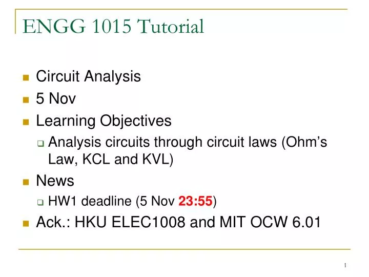
ENGG 1015 Tutorial. Circuit Analysis 5 Nov Learning Objectives Analysis circuits through circuit laws ( Ohm’s Law, K C L and KVL) News HW1 deadline (5 Nov 23:55 ) Ack.: HKU ELEC1008 and MIT OCW 6.01. Quick Checking. What is a Circuit?. Circuits are connects of components

E N D
ENGG 1015 Tutorial • Circuit Analysis • 5 Nov • Learning Objectives • Analysis circuits through circuit laws (Ohm’s Law, KCL and KVL) • News • HW1 deadline (5 Nov 23:55) • Ack.: HKU ELEC1008 and MIT OCW 6.01
What is a Circuit? • Circuits are connects of components • Through which currents flow • Across which voltages develop
Rules Governing Flow and Voltages • Rule 1: Currents flow in loops • The same amount of current flows into the bulb (top path) and out of the bulb (bottom path) • Rule 2: Like the flow of water, the flow of electrical current (charged particles) is incompressible • Kirchoff’s Current Law (KCL): the sum of the currents into a node is zero • Rule 3: Voltages accumulate in loops • Kirchoff’s Voltage Law (KVL): the sum of the voltages around a closed loop is zero
Rules Governing Components • Each component is represented by a relationship between the voltage (V) across the component to the current (I) through the component • Ohm’s Law (V = IR) • R: Resistance
Question 1: Current and Voltage • If R = 0 ohm, I1 = • If R = 1 ohm, V1 =
Solution 1 • If R = 0 ohm, I1 = 6V/3 ohm = 2A • If R = 1 ohm,
Parallel/Series Combinations • To simplify the circuit for analysis Series Parallel
Voltage/Current Divider Voltage Divider Current Divider
Question 2a: Voltage Calculation • Find V2 using single loop analysis • Without simplifying the circuit • Simplifying the circuit
Solution 2a • Choose loop current • Apply KVL • Replace V2 by R2I • Find V2
Solution 2b • Simplify the circuit with one voltage source and one resistor • Req. = R1 + R2 + R3 = 7 ohm • Veq. = Vs1 + Vs2 + Vs3 = -2 + 2 + 2 = 2 V • I = Veq. / Req. = 2/7 A • V2 = 4/7 v
Question 3: Potential Difference • Assume all resistors have the same resistance, R. Determine the voltage vAB.
Solution 3 • Determine VAB • We assign VG=0
Question 4: Current Calculation using Parallel/Series Combinations For the circuit in the figure, determine i1 to i5.
Solution 4 • We apply: • V = IR • Series / Parallel Combinations • Current Divider (i) (ii) (iii) (iv)
Solution 4 (vi) (vii) (v)
Question 5: Resistance Calculation using Parallel/Series Combinations Find Req and io in the circuit of the figure.
Solution 5 (i) (ii)
Solution 5 (iii)
Analyzing Circuits • Assign node voltage variables to every node except ground (whose voltage is arbitrarily taken as zero) • Assign component current variables to every component in the circuit • Write one constructive relation for each component in terms of the component current variable and the component voltage • Express KCL at each node except ground in terms of the component currents • Solve the resulting equations • Power = IV = I2R = V2/R
Question 6: Circuit Analysis (I) R1 = 80Ω, R2 = 10Ω, R3 = 20Ω,R4 = 90Ω, R5 = 100Ω Battery: V1 = 12V, V2 = 24V, V3 = 36V Resistor: I1, I2, …, I5 = ? P1, P2, …, P5 = ?
Solution 6a Step 1, Step 2 VN = 0 I1: M R5 V1 R1 B I2: M V3 R3 R2B I4: M V2 R4 B
Solution 6a Step 3 VM – VB = R5I1 + V1 + R1I1 I1 = (VM – VB – V1)/(R5 + R1) = (24– VB)/180
Solution 6a Step 3 VN– VB = R2I2 + R3I2 I2 = (VN– VB)/(R2 + R3) = – VB/30
Solution 6a Step 3 VM – VB = V2 + R4I4 I4 = (VM – VB – V2)/R4 = (12– VB)/90 We get three relationships now (I1, I2, I4)
Solution 6a Step 4, Step 5 KCL of Node B: I1+ I4+I2= 0 (24– VB)/180 + (12– VB)/90 – VB/30 = 0 VB = 16/3 V
Solution 6a Step 5 I1 = (24– VB)/180 = 14/135 A = 0.104A I4 = (12– VB)/90 = 2/27 A = 0.074A I2 = –VB/30 = – 8/45 A = – 0.178A
Solution 6a (6.66V, 90Ω) P = I2R = P1 = (0.104)2 80 = 0.86528W P4 = (0.074)2 90 = 0.49284W = VR42 / R
Solution 6b Let’s try another reference ground VM = 0 I1: B R1 V1 R5 M I2: B R2 R3V3 M I4: B R4 V2 M
Quick Checking I1: B R1 V1 R5 M I2: B R2 R3V3 M I4: B R4 V2 M Different direction, different result?
Solution 6b KCL of Node B: I1 + I2 + I4 = 0 VB – VM = R1I1 – V1+ R5I1 I1= (VB – VM + V1)/(R1 + R5) = (VB + 12)/180
Solution 6b VB – VM = R2I2 + R3I2 – V3 I2= (VB – VM + V3)/(R2 + R3) = (VB + 36)/30
Solution 6b VB – VM = R4I4 – V2 I4= (VB – VM + V2)/R4 = (VB + 24)/90
Solution 6b KCL of Node B: I1 + I2 + I4 = 0 (VB + 12)/180 + (VB + 36)/30 + (VB + 24)/90 = 0 VB = – 92/3 V
Solution 6b I1 = (VB + 12)/180 = –14/135 A = – 0.104A I2 = (VB + 36)/30 = 8/45 A = 0.178A I4 = (VB + 24)/90 = –2/27 A = – 0.074A
Question 7: Circuit Analysis (II) • Find vo in the circuit of the figure.
Solution 7 • Step 1: Define the node voltage (v1,v2,v3) • Step 2: Define the current direction
Solution 7 • Apply: 1) V = IR 2) KCL • Step 3: Consider node 1
Solution 7 • Step 3: Consider node 2 • Step 4, 5: From (1) and (2),v1 = 30V, v2 = 20V, v0 = v2 = 20V