Download
1 / 55
570 likes | 837 Views
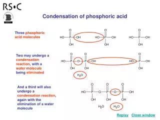
Review of Energetic Condensation. Larry Phillips October 9, 2006. ENERGETIC CONDENSATION. Introduction RF Performance and Properties of Sputtered Niobium Films Methods of Energetic Condensation Energetic Condensation Processes Energetically Condensed Niobium Films. ENERGETIC CONDENSATION.

E N D
Review of Energetic Condensation Larry Phillips October 9, 2006
ENERGETIC CONDENSATION • Introduction • RF Performance and Properties of Sputtered Niobium Films • Methods of Energetic Condensation • Energetic Condensation Processes • Energetically Condensed Niobium Films
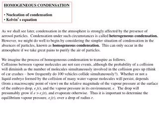
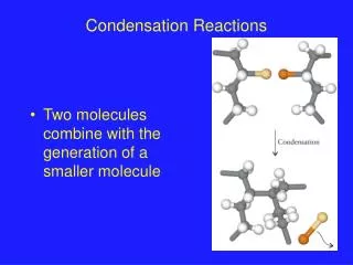
ENERGETIC CONDENSATION Introduction • The process of energetic condensation also known as hyper thermal condensation is that of adding energy to a film condensing from vapor to solid for the purpose of modifying its properties. • The methods used can be further classified as ion beam assisted deposition (IBAD) or direct ion deposition. • The basic problem with thermally deposited refractory metals is illustrated by the “Zone Structure Chart.”
Energetic Condensation • The problem: high melting point film deposition on a low temperature substrate- Ts<<Tm - high surface binding energy - low surface mobility –almost instant sticking • Zone 1 -lack of surface mobility -random direction of incoming vapor atoms -shadowing loose fibrous structure, voids, porosity
Energetic Condensation • Zone T - transition between Zones 1 and 2 (Thornton) - more tightly packed fibrous grain structure but not fully dense • Zone 2 - Ts ~ < 0.3 Tm - fully dense columnar grain structure with long columns extending from substrate to film surface • Zone 3 - Ts ~ > 0.45 Tm – no longer columnar –recrystallized with random orientation
Energetic Condensation • The purpose of using energetic condensation is to improve film structure on low temperature substrates by adding energy to the film during condensation to compensate for the lack of thermally induced growth processes. • One process, ion beam assisted deposition, (IBAD) uses a secondary source of ions to co-bombard the film from conventional sources during growth. • A second process, direct ion deposition, uses vacuum plasmas formed from the metal being deposited to produce a film grown from metal ions. • In both processes only the ion energies are adjustable.
Energetic Condensation • Niobium melting point = 2485 C. - for Ts = 100 C, Ts/Tm = 0.15 - for Ts = 300 C, Ts/Tm = 0.23 We might expect typical sputtered cavity to be in Zone T • ZSM modification by adding ion energy ( Messier) substitutes ion impact energy for thermal energy to induce adatom and subsurface mobility • Another ZSM modification ( Kelly and Arnell) includes the effects of ion energy and ions/atom
LIMITATIONS OF CONVENTIONAL MAGNETRON SPUTTERING FOR THIN FILM SRF CAVITIES • Microstructure defects and voids • Caused by lack of condensate mobility, shadowing • Results in enhanced intergranular oxidation producing “weak links” and associated problems and electronic mean free path limitation • Small grain size • Provide an upper limit to the electronic mean free path in the absence of other limiting impurities. • Sputter gas inclusion in the growing film along with other impurities such as oxygen and hydrogen. • Film to substrate adhesion and film stress.
RF PERFORMANCE OF SPUTTERED FILMS • Q drop is the primary performance limitation in sputter-deposited niobium cavities. It is more severe than in bulk niobium and the reasons have not been solidly identified. Some explanations have been suggested: • Heavy oxide penetration of the surface at grain boundaries and low density voided structure creates “weak links” interrupting the surface transport current and enables the entry of Josephson fluxoids • A dirty surface layer model proposed by Palmieri describe the field dependence of Q drop at all field regions.
RF PERFORMANCE (CONT.) • A depressed Hc1 at the surface arising from a small electronic mean free path enables fluxoid entry and large RF losses. • What do we know about the microstructure and superconducting properties of sputtered films which might relate to RF performance? • Sputtered films are known to have high values of Hc2 (low Hc1). • Grain size is small, typically 20-30 nm, but ~200 nm to 1 micron in some films. Large grain sputtered films still have low RRR values indicating grain boundary scattering is not dominating the defect density.
RF PERFORMANCE (cont.) • Oxygen and other impurity content: Recent measurements by Hand and Frisken for the ratio of impurity content of a CERN film (RRR=11.5) to bulk niobium (RRR=282) to be 5.9 for oxygen and 0.3 for hydrogen. These values are saturated with depth and the first 50 seconds of the SIMS trace shows a pronounced peak for oxygen not seen in the bulk niobium trace. • Also Hc1 measurements for these films with a Squid Magnetometer may not be a sensitive indictor of the local surface Hc1.
RF Performance • The best magnetron sputtered cavities to date are probably those from the CERN group. - adhesion is no longer a problem - grain size greater than 1 micron is achieved • bulk niobium performance is still not reached • What are the physical differences between these films and bulk material in the first 100 nm ? - low RRR and high Hc2- What limits mfp ? - Is there an influence from grain boundary structure on film properties in the first 100 nm ? • What is the difference in oxygen content profile ?
METHODS OF ENERGETIC CONDENSATION • Ion beam assisted deposition • Independent metal vapor and ion source • Electron beam ionization of metal vapor source • High Power pulsed magnetron • Unbalanced magnetron • Biased magnetron • Direct ion deposition • Vacuum arc deposition • ECR vacuum plasma • Metallic Plasma Pulsed Ion Immersion Implantation Deposition (MPIIID)
Beam systems for energetic condensations: • combined evaporation and ion beam system, • dual ion beam system, • evaporation with ionizing electron beam, • ionized cluster beam.
Biased Grid +100 V Cathode - 250 V Magnet Grounded Cavity
Energetic Condensation Processes • Densification and Defects • -at low ion energies densification is enhanced through increased surface mobility • - at a few hundred eV an ion will penetrate the surface a few nm and also lose energy through collisions with subsurface atoms (subplantation) in a collision cascade aiding densification ( Karl-Heinz Mueller, J. Appl. Phys. 59, 1986, 2803)
Energetic Condensation Processes • Densification processes cont. - Energy transfer to knock-on atoms ~10E-13 sec. - Collisional cascade, thermalization ~10E-11 sec. - Fills sub-surface voids • at high energies the rate of defect creation can exceed defect annealing
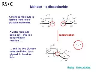
(a) (b) Si-film microstructure from Ref (37), (a) without argon ion bombardment where the energy distribution of the Si atoms is that Eq. (13); (b) with 50 eV argon ion bombardment and an atom-to-ion ratio of 0.5 Ferrow et al.
Energetic Condensation Processes • a niobium example (Hong Ji, et al, J. Appl. Phys. 81,1997,6754 ) - column size increases with ion energy - porosity increases with ion energy • bias sputtered niobium films – defect density with ion energy (Kay and Heim, J. Appl. Phys.49, 1978, p 4862)
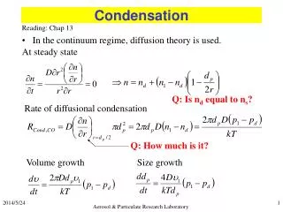
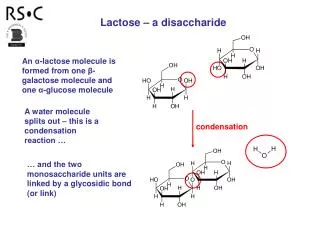
Residual resistivity due to lattice defects, ρdef, for various bias energies EB and two different substrate temperatures. The abscissa is the normalized krypton intensity jKr
Energetic Condensation Processes B. Preferential Sputtering and Channeling • Channeling: ions penetrate to a greater depth when impact is parallel to lattice planes and give up a smaller fraction of their energy at the surface • Ions striking in a channeling direction will have a lower sputtering yield leading to preferential sputtering • Preferential sputtering leads to preferred grain orientations which are sputtered slower and eventually dominate the film • This process can also create crevices leading to voids after being covered over by new deposits
Energetic condensation Processes C. Processes affecting electron scattering • Electron mfp must be much larger than the coherence length to avoid depressing Hc1. It is not needed for thermal conductivity due to the high conductivity of aluminum or copper substrates. • Significant scattering mechanisms in niobium films: - grain boundaries - volume defects, voids, strain, dislocations, etc. - impurities: oxygen, hydrogen, and in IBAD processes Ar or Kr
Energetic condensation Processes • Triode sputtered Palladium example, (Ziemann and Kay, J. Vac. Sci. & Tech. A1 (2) 1983, 512 - Krypton content, RRR, and grain size as a function of normalized ion energy - decline in Krypton content above 70 eV/atom is due to difference in re-sputtering rates of Kr, Pd, and the probability of Kr trapping with energy
Energetic Condensation Processes D. Surface Roughness • It is difficult to compare surface roughness between IBAD and vacuum ion plasma processes for several reasons: - a biased metal ion beam arrives nearly normal to the surface while an independent ion gun is at an angle to the surface - normalized ion energy energy cannot be directly compared with ion energy
Energetic Condensation Processes • Two examples: • Hong Ji, et al J. Appl. Phys. 81, 1994, 6754 - e-beam niobium vapor source with a Kaufman ion gun at 45 degrees to the substrate - roughness versus normalized ion energy G. Keppel, et al, “Comparison Between the Morphology of Superconducting Niobium Films by Magnetron Sputtering and Cathodic Vacuum Arc” -roughness versus deposition angle for 100 volt bias
ENERGETIC CONDENSATION PROCESS • Improvement in adhesion • Effective surface cleaning at ~25 eV/ion and above. • Atomic mixing across the substrate-film interface (ion stitching). • For metal ion deposition in vacuum this process is highly effective by using high ion energies at the beginning of the deposition followed by the energy desired for film growth for the rest of the film. • Lattice damage
Niobium Ion Vacuum Plasma Films • Some X-ray Diffraction results from the JLAB ECR process on copper substrates as a function of substrate bias (G.Wu, et al, Thin Solid Films, 489 (2005) 56 - films become more ordered with increasing ion energy - RRR values up to 50 are achieved on sapphire substrates- source of defects has not been established
Niobium Ion Vacuum Plasma Films • Two important RF results by vacuum arc deposition: • L. Catani, et al, SRF 2005 Proc., Cornell University - uses film nonlinearity as a mixer to measure changing surface impedance with field • Romanko and Russo, SRF 2005, Proc., Cornell University - TE011 cavity shows near constant surface impedance up to 450 Oe.