Download
1 / 71
710 likes | 838 Views
LISA Interferometry TeV II Meeting Madison, Wi August 30 th , 2006. Guido Mueller University of Florida. mueller@phys.ufl.edu. LISA. 1. Super-massive Black Hole mergers. Gravitational Wave Sources. Chandra: NGC6240. 2. Extreme mass ratio Inpirals (EMRIs).

E N D
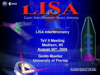
LISA InterferometryTeV II MeetingMadison, WiAugust 30th, 2006 Guido Mueller University of Florida mueller@phys.ufl.edu
LISA 1. Super-massive Black Hole mergers Gravitational Wave Sources Chandra: NGC6240 2. Extreme mass ratio Inpirals (EMRIs) 3. Galactic Binaries 4. … Credit: Tod Strohmayer (GSFC)
LISA vs. LIGO LISA: Joint NASA/ESA project LIGO: NSF project Advanced LIGO EMRIs
LISA Concept LISA Concept: • 3 Spacecraft in triangular formation • 5 Gm distance betw. S/C • Heliocentric Orbit • Measure changes in distance with 10pm/rtHz accuracy! Movie
LISA Technical Challenges: • How to build a gravitational reference sensor? • Need a non-accelerated proof mass acceleration < 3x10-15 m/s-2 / rHz • How to do pm-Interferometry over 5Gm? • Interferometry Measurement System (IMS)
LISA Interferometry • Goal: • Measure distances with • 10 pm/rtHz accuracy • Basics: • Laser: • Wavelength: 1mm • Power: 1 W • Telescopes: • f/1 - Cassegrain • Diameter: 40cm • Received power: ~100pW
The Main Problem The Orbit Problem: Arm lengths change by about 50.000km during 12mts orbit or by ~ 1m/s.
The Orbit Problem • Arm lengths change • by about 50.000km • during 12mts orbit • or by ~ m/s. • Doppler shifts (~ MHz)
The Orbit Problem • Arm lengths change • by about 50.000km • during 12mts orbit • or by ~ 1m/s. • Doppler shifts (~ MHz) • Unequal arm lengths • (frequency noise)
The Orbit Problem • Arm lengths change • by about 50.000km • during 12mts orbit • or ~1m/s. • Doppler shifts (~ MHz) • Unequal arm lengths • (frequency noise) • Telescope repointing (pointing noise) Very dynamic interferometer!
LISA Concept High Gain Antennas uN-Thrusters
LISA Concept Optical Benches Proof Mass Housing Telescopes
Interferometry • Main Components/Tasks: • Phasemeter • Laser Frequency Noise • Mechanical Noise (Solution: Engineering)
Phasemeter • Requirements: • 2-20 MHz signal frequencies, changing by several MHz • Frequency noise of 30Hz/Hz1/2 @ 1mHz • = 30000 cycl./Hz1/2 @ 1mHz • need to be resolved with 10-5 cycles/Hz1/2 accuracy! • Dynamic Range of 9 orders of magnitude.
Input I Q NCO Feedback The JPL Phasemeter Tracks the Phase of RF signal with NCO I/Q demodulation with tracking NCO
x107 zoom dynamic range ~109 @ 5 mHz Requirement The JPL Phasemeter Equivalent Optical Setup • Digitally tested dynamic range requirement. • Digitally generated 3 independent, laser-like noise sources such that, Phase 0+Phase 1- Phase 2 = 0 (Results from Daniel Shaddock, Brent Ware, Bob Spero, JPL)
Laser Frequency Noise • Requirements: • Frequency noise of 30Hz/Hz1/2 @ 1mHz (for Phase meter) • Free running laser: ~ 1MHz/Hz1/2 @ 1mHz • Everything below 30Hz/Hz1/2 reduces requirements • on Phase meter • Solution: • Frequency stabilization • Time Delay Interferometry
Frequency Stabilization Ground testing: • Two lasers independently stabilized to two reference cavities: • References: 2 Zerodur spacers with optically contacted mirrors in ultra-stable vacuum chamber • Pound Drever Hall stabilization scheme (Modulation/Demodulation) • 1st Step: Stabilize to ultra-stable reference cavity: • Baseline: ULE or Zerodur spacer ring cavity
Rachel Cruz Frequency Stabilization UF-results • Similar Results • with ULE spacers: • AEI Hanover • GSFC • Can we do better?
Arm Locking Basic Idea: Lock laser frequency to LISA arm Far S/C: Transponder (phase locked laser) ! S(t) = f(t-2t)-f(t) = 0 • Transfer function is zero at Fourier frequencies fN = N/2t • Requires tailored feedback gain (~1/sqrt(f)) at and above f1 up to UGF High bandwidth, only limited gain • Laser frequency noise suppressed at all frequencies except at fN = N/2t
Arm Locking Different potential realizations: Single Common Sagnac Round-trip arm length Difference between arms Sagnac effect (rotation)
Arm Locking Sagnac • Sagnac: • Allows high-gain, • low-bandwidth feedback loop • Very simple design • Main disadvantage: • No redundancy: • If one link malfunctions, • the Sagnac signal is gone • Common arm locking is the baseline Sagnac effect (rotation)
Stabilized “Reference” Stabilized “Master” Phase-locked “Slave” Interferometer & arm-locking Arm Locking
Arm Locking • Compare to LISA:
Arm Locking • Latest Arm Locking experiment at UF • currently limited by missing real time phasemeter • EPD using 25 MHz digitization rate, delay of 1.065ms or f1 = 939Hz
Arm Locking • Latest Arm Locking experiment at UF • currently limited by missing real time phasemeter • Out-of-loop • Primary beat note demodulated to 10kHz • Phase of 10kHz signal measured using software phase meter.
Arm Locking • Out-of-loop • Primary beat note demodulated to 10kHz • Phase of 10kHz signal measured using software phase meter. Ira Thorpe
Time Delay Interferometry • Laser frequency stabilization • Time Delay Interferometry (TDI) First Generation X-combination: Sb(t) -Sg(t) -Sb(t-2τg) +Sg(t-2τb) • Requires to know the light travel times betw. S/C • Ranging with 30m accuracy Synthetic equal arm Interferometer!
TDI Experiment (Nearly) full scale LISA signal Limited by Transponder Noise
TDI Experiment • Results currently limited by PLL performance 5 orders suppression Phase Noise [cycles/rt(Hz)] Rachel Cruz Frequency [Hz]
Summary LISA Interferometry: Requirements: • 10pm/rtHz in a dynamic 5Gm interferometer Key Technologies: • Phase meter • Laser frequency stabilization • Reference Cavity • Arm locking • Time Delay Interferometry
Summary ESA/EU: • ESA/Estec • Astrium, Germany • AEI Hanover • University Trento • University of Birmingham • University of Glasgow • … NASA/US: • GSFC • JPL • University of Florida • JILA • Stanford • University of Washington • … The End Lets get dinner! + many data analysis and theory groups
Summary LISA: • Remaining Challenges: • How to move the telescope w/o distorting the measurements? • Do we need to measure these distortions and correct for them? • How to align the spacecraft to acquire lock? • Stable materials and components: • Laser switch, Fiber launcher, Vacuum system, Discharging, PAA actuator, … • Data Analysis challenges • Galactic binaries create a GW “noise” floor Does this sound different from other missions?
Summary LISA: • GRS: • Will be flight tested in LTP around 2009/10 • LTP ground tests look very promising so far • Interferometry: • Basic concepts of TDI, Arm-locking, clock noise removal are well understood • Experimental tests at component level are progressing very well • EPD unit enables detailed ground testing of TDI/AL (Test as you fly, fly as you test)
Summary LISA: Was considered a very challenging mission • No ground testing possible • No technology heritage for any of the major technologies: • GRS • Interferometry • Data Analysis
400x Arm Locking • Out-of-loop measurement of primary beat note using frequency counter. Ira Thorpe
Delayed Prompt Prompt-Delayed TDI Experiment First experimental verification of TDI! Rachel Cruz, Michael Hartman, UF
UF Simulator Electronic Phase Delay • UF technique: • Laser Phase replaced by beat note phase • Beat note phase delayed electronically (EPD). • LISA photodiodes replaced by electronic mixers. LISA
Electronic Phase Delay Max. Signal System Date Hardware # Chan. Max. Delay Freq. Summer 200 kHz PCI Original 30 kHz 2 80 s 2004 card Summer Current Pentek 5 MHz 4 6 s 2005 Fall Pentek w/ Future 2 0 MHz 4 35 s * 2006 PMs & NCOs *Depends on resolution & BW
Short LISA History • Foundation paper in 1984 by Bender, Faller, Hall, Hils and Vincent • Concept developed through • Concept studies ‘84-’93 • ESA Pre-Phase studies ‘93-’98 (cf., PPA2 document) • NASA Team-X study ‘98 • ESA Industrial Phase A Study ‘98-’00 (cf., FTR and STS documents) • GSFC Project Office formed in ‘01, technology planning and development commenced. • Flight demonstrations (LISA Pathfinder and ST-7) initiated in ‘00-’01 • NASA Formulation Phase began Oct. ‘04 • ESA Industrial Formulation Study begun at Astrium/Friedrichshafen Jan. ‘05, finished Phase I in Oct. ‘05 • Concept has not significantly changed since PPA2 in 1998. • Current focus • Architecture definition and refinement, design trade studies • Technology development • LISA Pathfinder and ST-7 We entered Phase A late 2004! Slide stolen from Robin ‘Tuck’ Stebbins LISA Symposium Talk
Mission Status • ST7 brings the least well-tested LISA instrumentation, DRS, to TRL level 9 • Preparations for 2010 launch will already greatly enhance • Experience in building flight models • Experience in tightly-coupled NASA/ESA cooperation • Results from 2010 launch will be in time to inform formulation FY07 FY08 FY09 FY10 FY11 HW delivery launch Phase C/D Phase E Phase A (survival) Phase A Phase B Slide stolen from Colleen Hartman, LISA Symposium
Mission Status • Budget requirements have necessitated Beyond Einstein be sequential missions rather than parallel efforts • Funding wedge for first BE mission start in 2009 • One of 3 will go first: LISA, Con-X, JDEM • Special BE NRC panel in 2008-9 Instead of two parallel lines of sequential missions We hear you … JDEM: Additional competition! From Colleen Hartman, LISA Symposium
Optical Bench Phase Meter 2 Phase Meter 1 Phase Meter 3 Fiber to/from Second Bench to/from far SC PM from Laser Bench
Optical Bench Phase Meter 1 • Bench A: • PM1A: f1(t) -f2(t) + fibernoise • Bench B: • PM1B: f1(t) -f2(t) - fibernoise • PM1A + PM1B = 2 [f1(t) - f2(t)] • Independent of fiber noise • Used to phase lock local lasers • Allows to compare both Interferometer arms • [Like having a beam splitter in a Michelson Interferometer Fiber to/from Second Bench from Laser Bench Only works if OPL in fiber is independent of propagation direction!
Optical Bench Polarization Sagnac Interferometer for Optical Fiber Tests at UF Fiber Pol l/4 l/2 Laser l/4 BS Pol Parallel tests in Glasgow, Hanover
Optical Bench Phase Meter 2 Phase Meter 1 Phase Meter 3 Fiber to/from Second Bench to/from far SC PM from Laser Bench PM 2 – PM 1 : Distance PM - SC
Optical Bench Phase Meter 2 Phase Meter 1 Phase Meter 3 Fiber to/from Second Bench to/from far SC PM from Laser Bench PM 3: Distance SC – SC How?
Optical Bench • Phase Meter 3 on S/C 2 and 3: • Used to Phase lock local laser Phase Meter 3 PM 3A – PM 1A To Laser frequency actuator ]PLL to/from far SC PM from Laser Bench
LISA Master S/C Slaved S/C Slaved S/C
Optical Bench • Phase Meter 3 on Master S/C 1: Phase Meter 3 PM 1A – PM 3A • = f1(t)-f1(t-2t1)+GW1 • (~Unequal Arm MI) • Dominated by Laser frequency noise df : • ~1000 cycl./rtHz noise PM from Laser Bench to/from far SC