Aerobraking
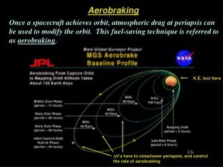
Aerobraking. Once a spacecraft achieves orbit, atmospheric drag at periapsis can be used to modify the orbit. This fuel-saving technique is referred to as aerobraking. K.E. lost here. D V’s here to raise/lower periapsis, and control the rate of aerobraking. The Aerobraking Process.

Aerobraking
E N D
Presentation Transcript
Aerobraking Once a spacecraft achieves orbit, atmospheric drag at periapsis can be used to modify the orbit. This fuel-saving technique is referred to as aerobraking. K.E. lost here DV’s here to raise/lower periapsis, and control the rate of aerobraking ASEN 5335 Aerospace Environments -- Upper Atmospheres - Aerobraking & Aerocapture
The Aerobraking Process • Once a spacecraft is in its initial orbit, a series of DV’s are employed at apoapsis to lower the orbit periapsis to the altitude at which aerobraking will occur. (Spacecraft heating is an issue if periapsis is too low.) ‘walk-in phase’ • The spacecraft then remains in this orbit until the apoapsis altitude approaches the desired orbital altitude. (This phase of the aerobraking process can take months, depending on how deep the spacecraft is allowed to dip into the atmosphere.) ‘main phase’ • At this point, DV’s can then be applied to raise periapsis to the desired final altitude, while perhaps lowering apoapsis. (Usually the final orbit to be achieved is circular.) ‘walk-out phase’ Advantages/Disadvantages • Aerobraking conserves fuel, mass, volume, and cost, for both spacecraft and launch vehicle. • Knowledge of the density and variability of the planet’s upper atmosphere is poorly known, increasing mission risk. • Aerobraking is a lengthy process, which can often last over several months. ASEN 5335 Aerospace Environments -- Upper Atmospheres - Aerobraking & Aerocapture
Aerobraking Experiment at Venus Magellan was the first orbiting planetary spacecraft to use atmospheric drag, or aerobraking, to change its orbit. (aerodynamic heating of the spacecraft was much less than expected) Composite SAR image of Venus from Magellan data Launched: May 4, 1989 Arrived at Venus: August 10, 1990 Initial orbit: Highly elliptical polar, 3-hr 15 min. orbit --> periapsis 294 km; --> apoapsis 8543 km Over the next 3 years, Magellan used radar to penetrate the dense cloud cover surrounding Venus and map its surface. An aerobraking experiment was then performed: May 25, 1993: periapsis lowered to 140 km August 3, 1993: aerobraking completed Final orbit: 180 x 541 km; 94 min. Atmospheric entry: 11 Oct 1994 - 14 Oct 1994 September, 1994: ‘windmill experiment’ the spacecraft's solar panels were turned to a configuration resembling the blades of a windmill, and Magellan's orbit was lowered. Flight controllers then measured the amount of torque control required to maintain Magellan's orientation and keep it from spinning, new information useful in designing future spacecraft. ASEN 5335 Aerospace Environments -- Upper Atmospheres - Aerobraking & Aerocapture
Artist’s Conception: Odyssey Spacecraft during Aerobraking Aerobraking at Mars: Odyssey The Odyssey spacecraft, which was launched in 2001, also successfully utilized aerobraking during its mission. • Odyssey skimmed through the upper reaches of the Martian atmosphere 332 times. • By using the atmosphere of Mars to slow down the spacecraft in its orbit rather than firing its thrusters, Odyssey was able to save more than 200 kilograms of propellant. • This reduction in spacecraft weight enabled the mission to be launched on a Delta II 7925 launch vehicle, rather than a larger, more expensive launcher. ASEN 5335 Aerospace Environments -- Upper Atmospheres - Aerobraking & Aerocapture
ASEN 5335 Aerospace Environments -- Upper Atmospheres - Aerobraking & Aerocapture
MGS Aerobraking: The Original Mission Plan Following orbit insertion, MGS began aerobraking Initial orbit: highly eccentric; 263 x 54,026 km ; T=45 hours; i = 93.26 deg Desired orbit: near-polar near-circular sun-synchronous (near-uniform coverage over most of the planet) Planned Aerobraking • Walk-in phase: The orbit periapsis is lowered from the capture orbit altitude of 263 km to the altitude at which aerobraking will occur through a series of small propulsive maneuvers. • The spacecraft will remain at the aerobraking altitude during the main phase for three months as the apoapsis altitude is slowly lowered from 54,000 km to about 2000 km and the orbital period is reduced to under 3 hours. • The final three weeks of aerobraking constitute walk-out which reduces the apoapsis altitude to 450 km while slowly increasing the periapsis altitude. ASEN 5335 Aerospace Environments -- Upper Atmospheres - Aerobraking & Aerocapture
Planned Aerobraking (cont.) • The descending orbit node location will have rotated from its initial position near 5:45 PM to nearly 2:00 PM. At this point aerobraking is terminated with a maneuver which raises periapsis out of the region of significant drag. • Following the completion of aerobraking, final mapping orbit adjustments are made and the spacecraft and instruments are prepared for the start of mapping which will begin in March 1998. Mapping will continue for a full Mars year (687 days). Risk Aspects of MGS Aerobraking: In contrast to Magellan at Venus, aerobraking precedes the main mapping activity; therefore mission success depends on successful aerobraking Science constraints require 2:00 pm sun-synchronous orbit. Aerobraking must proceed on a schedule such that this constraint is met at the end of aerobraking. ASEN 5335 Aerospace Environments -- Upper Atmospheres - Aerobraking & Aerocapture
Walk-in Phase Maneuver DV (m s-1) Periapsis (km) r & rV2 (kg km-3; N m-2 ) -------------- ------------- -------------------- ---------------------------------- 3 AB-1 4.4 149.3 0.36; 0.00 at P4 4 AB-2 0.8 128.4 5.61; 0.06 at P5 5 AB-3 0.3 121.4 10.7; 0.12 at P6 7 AB-4 0.2 116.1 20.1; 0.23 at P8 10 AB-5 0.2 111.2 42.2; 0.49 at P11 11 AB-6 0.05 110.5 45.7; 0.53 at P12 Note: The first periapsis that occurred during the MOI maneuver is designated as P1 Actual Aerobraking • Aerobraking was initialized by gently stepping into the atmosphere by lowering the periapsis altitude through a series of small propulsive maneuvers executed at apoapsis. ASEN 5335 Aerospace Environments -- Upper Atmospheres - Aerobraking & Aerocapture
MGS Aerobraking configuration The aerobraking process begins with the spacecraft configuring itself in an orientation to increase drag. Both Magellan and Mars Global Surveyor used their flat solar panels and high gain antenna dishes to provide a large profile area. MGS also released extra flaps located at the end of the solar panels to further increase the drag. Simulation of the reconfiguration of the solar arrays on the Mars Global Surveyor spacecraft for Aerobraking. The reversal of the minus y-axis solar panel is a result of that panel not latching after initial deployment just after launch ASEN 5335 Aerospace Environments -- Upper Atmospheres - Aerobraking & Aerocapture
MGS Aerobraking: Main Phase Aerobraking and Temporary Suspension • • The next phase, called the main phase, was defined by a dynamic pressure corridor with upper and lower limits being 0.68 Nm-2 and 0.58 Nm-2 respectively. • The upper limit provided for adequate orbit period reduction and safety against aerodynamic heating of critical spacecraft components. • The lower limit insured a minimum level of orbit period reduction. • • Shortly after beginning the main phase, a problem with the minus-Y axis solar array developed which necessitated a temporary suspension of aerobraking. • Periapsis was raised to 172 km to look at the problem. ASEN 5335 Aerospace Environments -- Upper Atmospheres - Aerobraking & Aerocapture
MGS Aerobraking: Main Phase Aerobraking and Temporary Suspension • If further aerobraking was not possible, this could severely impact the mission. For instance, the Mars Orbiter Laser Altimeter (MOLA) could only acquire a return signal when the range to the surface was less than about 780 km. • In addition, because aerobraking had been halted, it was no longer possible to reach the 2:00 PM equator crossing orbit for which the mission was designed. This orbit was also necessary to optimize power and communications with earth. • After an engineering evaluation, it was concluded that one of the face sheets of the yoke attaching the solar array to the gimbel motor had sustained a crack. The revised plan called for a reduced level of aerobraking, thus subjecting the solar array to less aerodynamic stress. • The new dynamic pressure corridor was set to 0.15 to 0.25 Nm-2. ASEN 5335 Aerospace Environments -- Upper Atmospheres - Aerobraking & Aerocapture
Solar conjunction, May of 1998. Communications unreliable. Peripasis temporarily raised to 170 km. Aerobraking halted. No science measurements. MGS Aerobraking: Phases I and II The second phase of aerobraking did not need to start until fall, 1998, so the intervening six months were used for science observations (‘Science Phasing Orbit’) with the spacecraft pointing the instruments toward the planet at each periapsis. about 700 orbits one year later than planned about 200 orbits Note: The original aerobraking plan was for 300 orbits; instead it took ~900 orbits and 1 additional year. ASEN 5335 Aerospace Environments -- Upper Atmospheres - Aerobraking & Aerocapture
Highly variable Density decline precessing into N. Hemis. winter MGS Aerobraking: Variability of Density at Periapsis Variations in atmospheric density can be appreciable, requiring orbit by orbit evaluations by the flight team to determine whether or not the periapsis altitude should be lowered to maintain a steady decrease in orbit period, or increased to avoid large forces on the solar arrays. The Density Measured at Each Periapsis is Extrapolated to a Constant Altitude of 122 km and Plotted in this Figure For Orbits 80-150 (2 January 1998-27 February 1998). The Smooth Green Curve is a Least Squares Exponential Fit to the Points Shown, Illustrating the Slow Decline in Atmospheric Density Experienced as the Spacecraft Periapsis Moved North into N. Hemisphere Winter. ASEN 5335 Aerospace Environments -- Upper Atmospheres - Aerobraking & Aerocapture
The Extrapolated Periapsis Density at an Altitude Of 122 km as a Function of the Periapsis Longitude for Orbits 80-150. The Smooth Green Curve is a Least Squares Fit to the Data Using a Constant Term, Two Sine Terms, one Wave-1 and one Wave-2. MGS Aerobraking: Variability of Density at Periapsis One of the unanticipated results from aerobraking in the Northern hemisphere of Mars is the discovery that there is a longitude dependence to the density variations which is related to surface topography. ASEN 5335 Aerospace Environments -- Upper Atmospheres - Aerobraking & Aerocapture
+5 0 -5 Change in period, min -30 20 40 60 160 180 Apoapsis Number Period Changes Per Orbit During Phase I Aerobraking MGS Aerobraking: Variability of Orbital Period Between orbits 40 and 60, a dust storm occurred that inflated the atmosphere and caused the density at periapsis to increase by 133%. The periapsis was raised until the storm effects subsided. It did not turn out to be as large a storm as some in the past. The design had a margin of 90% with respect to unpredictable changes in atmospheric mass density at periapsis. This means that the spacecraft could tolerate at least an unpredicted change of 90% in the periapsis density without exceeding a heating constraint of 0.68 Wcm-2 (given the 17 m2 projected area of the spacecraft this corresponds to a maximum dissipation of 116 kilowatts near periapsis). ASEN 5335 Aerospace Environments -- Upper Atmospheres - Aerobraking & Aerocapture
Aerocapture Aerocapture is similar to aerobraking, except only one pass through the atmosphere is employed to place the spacecraft into its final orbit. Aerocapture is very attractive for planetary orbiters since it permits spacecraft to be launched from Earth at high speed, to give a short trip time, and then reduce the speed by aerodynamic drag at the target planet. Without aerocapture, a large propulsion system would be needed on the spacecraft to perform the same reduction of velocity, thus reducing the amount of delivered payload. Aerodynamic and heat protection constraints are placed on a spacecraft to be aerocaptured. These functions can be satisfied using a traditional blunt, rigid aeroshell (see figure); by a potentially lighter inflatable aeroshell; or by a large trailing ‘ballute’, a combination parachute and balloon made of durable, thin material. Each of these are discussed in the following. ASEN 5335 Aerospace Environments -- Upper Atmospheres - Aerobraking & Aerocapture
Aerobraking: Advantages, Disadvantages, Challenges Advantages Reduces braking time dramatically - from months to hours - reducing continuous ground control operations and overall mission costs. Shortened flight time, therefore attractive for human missions. Disadvantages High integrated heat loads (high entry velocity) Risky Thermal Protection System (TPS) - expensive, consumes mass (less than the fuel needed for thrust maneuvers.) Challenges Heat-shield Technology. Autonomous, closed-loop guidance and control systems are required. Detailed atmospheric information required. Aerocapture flight speeds can not be duplicated in a lab. Therefore, flight test data such as flow field structure, aerothermochemistry, and aerodynamic forces are needed. ASEN 5335 Aerospace Environments -- Upper Atmospheres - Aerobraking & Aerocapture
Aerocapture Scenario • The aerocapture maneuver begins with a shallow approach angle to the planet, followed by a descent to relatively dense layers of the atmosphere. • Once the needed deceleration is reached, the vehicle maneuvers to exit the atmosphere. • To account for the inaccuracies of atmospheric entry and atmospheric density, the vehicle must have autonomous guidance and control and maneuvering capabilities. The entire operation requires the vehicle to operate autonomously while in the planet's atmosphere. • Most maneuvering is done using the lift vector that the vehicle's aerodynamic shape (i.e., lift-to-drag ratio, L/D) provides. L/D ~ 1.5 meets requirements. • Upon exit, the heatshield is jettisoned to minimize heat soak and a short propellant burn is accomplished to raise the orbit periapsis. ASEN 5335 Aerospace Environments -- Upper Atmospheres - Aerobraking & Aerocapture
AEROBRAKING / AEROCAPTURE VEHICLE TYPES There are several vehicle shapes under consideration for aerocapture missions: raked cones (non-symmetric) bent-cones (biconics) winged gliders The predominant geometry are the so-called raked cones, which employ blunt, hard-shelled aerobrakes, that are most applicable to high-speed aerocapture. Orbit Transfer Vehicle (OTV) with Raked-Cone Aeroshell. ASEN 5335 Aerospace Environments -- Upper Atmospheres - Aerobraking & Aerocapture
Biconic Aerocapture Vehicle The bent-cone (biconic) shape can produce a lifting-body effect. Biconic shapes represent a good compromise that allows high-velocity aerobraking along with the ability to perform plane (angle of inclination) changes. Two articulated control surface "vanes" or "flappers" are located in the rear to provide differential drag for attitude control during the aeromaneuver. Biconic Aerocapture Vehicle Aerocapture at Mars with Biconic Aeroshell For the biconic aeroshell, the main engines can be placed at the front (nose) of the aeroshell (as shown), or at the rear, depending on the specific application. ASEN 5335 Aerospace Environments -- Upper Atmospheres - Aerobraking & Aerocapture
WRAP RIB AEROBRAKE This is a reusable umbrella-like system that could unfold during aerobraking (see Mars aeroshell application). Aerodynamic forces require a sturdy "rib" arrangement for the aerobrake itself, thus increasing the weight of the system. These weight considerations are the main drawback of the design, though changes in vehicle configuration may alleviate this problem. This configuration is somewhat similar to that used by the Magellan spacecraft to aerobrake from an elliptical to a circular orbit around Venus, and MGS aero- braking at Mars. In these cases, the orbit was circularized gradually by multiple passes through the atmosphere, so the solar arrays could be used as the primary aerobraking surface. ASEN 5335 Aerospace Environments -- Upper Atmospheres - Aerobraking & Aerocapture
Aerocapture for Manned Exploration of Mars For one manned Mars exploration scenario developed by the Global Aerospace Corporation, routine visits to Mars would be accomplished using an Interplanetary Rapid Transit (IRT) System involving taxi from Earth orbit or Spaceport, aerocapture at Mars to decelerate, transfer to Mars shuttle at Mars spaceport, and then Mars Shuttle to Mars base. Aerocapture at Mars - Elliptical Raked Cone Aeroshell Mars Aerocapture Profile ASEN 5335 Aerospace Environments -- Upper Atmospheres - Aerobraking & Aerocapture
Atmospheric Entry at Mars Using Aerobraking ASEN 5335 Aerospace Environments -- Upper Atmospheres - Aerobraking & Aerocapture
SATURN / TITAN AEROCAPTURE WITH BICONIC AEROSHELL An example of outer-planet aerocapture might be a mission to Saturn/Titan. In this mission, a spacecraft would approach Saturn's moon Titan from behind in Titan's orbit. The spacecraft would be catching up to Titan so as to reduce the speed of entry into Titan's atmosphere by the amount of Titan's orbital velocity about Saturn. Once in Titan's atmosphere, spacecraft speed would be reduced enough by atmospheric drag to fall into an elliptical orbit about Saturn. This would permit close inspection of Saturn and several of its moons with the option of later aerocapture into an orbit about Titan. ASEN 5335 Aerospace Environments -- Upper Atmospheres - Aerobraking & Aerocapture
AEROGRAVITY-ASSIST MANEUVERS Aerogravity-assist involves the same concept as gravity-assist maneuvers except that it involves the use of a planet's atmosphere. The idea is that with large planets, such as Jupiter, gravity-assist maneuvers are very efficient due to the high gravitational field of the planet and therefore to the high turning angle (~90°) that they can provide. The increase in velocity during a gravity assist maneuver is related to the turning angle (amount of bending) or gravitational field of the planet. For planets with small gravitational fields, like Venus, Mars, Earth, a way to increase this turning angle is to use their atmospheres and the lifting capabilities of the vehicle. ASEN 5335 Aerospace Environments -- Upper Atmospheres - Aerobraking & Aerocapture
Consider the extreme case: Conservation of kinetic energy and momentum for the spacecraft- planetary system yield: where the upper (lower) case letters refer to the planet (spacecraft), respectively Eliminating U2 and solving for v2 yields: ASEN 5335 Aerospace Environments -- Upper Atmospheres - Aerobraking & Aerocapture
AEROGRAVITY-ASSIST USING WAVERIDERS Tilting the vehicle downward during the atmospheric flight will move its trajectory toward the planet and increase the overall angle that the vehicle has turned on a planetary scale. The amount of angular deflection is directly proportional to the vehicle's lift-to-drag ratio (L/D). 4.5 Waveriders Optimized to M20, M10, M5 3.0 Atmosphere Total L/D Planet Bicone 15% Blunt 1.5 sphere of influence 0.0 Aerogravity-assist typically uses high lift, low-drag sharp edged waverider vehicles, for which high temperature resistant materials are critical. This technology is much further from reality than aerocapture. It is however a far-reaching capability that could have significant impact on the mass and/or time of flight for distant missions. ASEN 5335 Aerospace Environments -- Upper Atmospheres - Aerobraking & Aerocapture
Developing Technology: Direct-Entry Probe For this class of direct-entry probes, the aeroshells are carried to the surface where they shatter on impact. There are no deployables, parachutes, or airbags to assist in the entry and landing. The entry system is designed to passively orient itself upon atmospheric entry prior to peak atmospheric heating. Thus, the probes are not required to be spin stabilized on release, nor do they need an active attitude guidance and control system (e.g., thrusters or rockets). The microprobes are nestled in the nose of the aeroshell to ensure the system's center-of-mass is lower than its center-of-gravity. This helps to ensure the probes always land "right side up", similar to a badminton birdie. ASEN 5335 Aerospace Environments -- Upper Atmospheres - Aerobraking & Aerocapture
Trajectory Simulation for Mars Microprobe Like a javelin, the probe needs to hit the surface at the right angle or it may never penetrate. ASEN 5335 Aerospace Environments -- Upper Atmospheres - Aerobraking & Aerocapture
Advanced heatshield material called SIRCA-SPLIT (Silicon-Impregnated Reusable Ceramic Ablator - Secondary Polymer Layer-Impregnated Technique) Aftshell and Heatshield Ready for Final Assembly. Aeroshell Fully Assembled. Probe is Installed into the Heatshield. light weight <1.2 kg Heat shield capable of withstanding surface temperatures up to 2000° C while maintaining the probes internal temperature to within a few degrees of -40 C. Brittle silicon carbide aeroshell structure - shatters on impact ASEN 5335 Aerospace Environments -- Upper Atmospheres - Aerobraking & Aerocapture
BALLUTES Another aerobraking design is the ballute (an inflatable balloon-parachute), made from a thin, flexible, inelastic membrane. A very dramatic example of aerocapture into Jupiter orbit using a ballute system was depicted in the movie "2010, The Year We Make Contact". Attached Ballute Cocoon Ballute Tethered Ballute One option is to have the main spacecraft engine run at low idle thrust during aerocapture to provide an aerodynamic "spike" to reduce heating on the ballute. ASEN 5335 Aerospace Environments -- Upper Atmospheres - Aerobraking & Aerocapture
Ballute Technology Assessment Aerocapture ballutes are in an early stage of technological development. Unresolved Ballute Technical Issues Issue Description Optimal Shape Which shape (sphere, disk, toroid, ?) for which missions? Survivability Can the membrane material survive the heating and drag? Flow stability If the flow is not stable, can its effects be tolerated? System mass Will ballutes be low mass enough to be competitive? Trajectory How to compensate for atmospheric uncertainties? Structure How to ensure structural integrity? Tether Can the tether(s) be designed to take the heating and stress? Parent Vehicle What auxiliary thermal and aerodynamic protection does the spacecraft require? Can its mass be tolerated? Deployment & inflation Can this technology be borrowed from other inflatable efforts? Experimental verification What is a good ground vs space testing mix? A few of these are now discussed to give an overall sense of the issues …. ASEN 5335 Aerospace Environments -- Upper Atmospheres - Aerobraking & Aerocapture
Optimal Shape Single-Tether • doesn’t have Cocoon problem of deploying and Towed Ballute removing membrane around solar panels, etc. • easily detached from parent spacecraft • separates ballute and spacecraft, preventing lateral forces (i.e., due to unsteady shock waves, vortex shedding, etc.) Spherical Ballute: Drag & heating insensitive to orientation However, inflation gas mass d3 envelope mass d2 Tether aligned with flow, minimizing tether heat load Other shapes need to be investigated with an eye on mass, flow and heating characteristics ASEN 5335 Aerospace Environments -- Upper Atmospheres - Aerobraking & Aerocapture
Survivability of Ballute Material Heat fluxes on ballutes (compared to aeroshells) are lower, due to their (a) large size; (b) shallow entry angle; (c) peak heating at higher altitude (lower density). Ballutes can self-cool by radiated energy emission (blackbody emission) at a tolerably low temperature. Possible material: Laminates of Kapton film (to retain the inflation gas) and PBO (polybenzoxazole) fiber (for strength and durability), possibly with a high-emissivity coating for radiative cooling. Deployment and Inflation Technologoy exists for deployment and inflation. However, pressurized gas will heat up in ballute, and a pressure relief mechanism may be necessary. This may add a significant mass penalty. Verification High velocities and planetary compositions cannot be duplicated on the ground; therefore, flight testing will eventually be necessary. ASEN 5335 Aerospace Environments -- Upper Atmospheres - Aerobraking & Aerocapture
Ballute Flow Stability and Heating Stability and heat transfer considerations are critical, as ballutes are aerodynamically unstable at high Mach numbers, and radiative heat transfer is significant. Large lateral forces can be exerted on the ballute due to vortex shedding. Flow instabilities can result due to wake and shock wave interactions between the ballute and spacecraft. Toroidal-shaped ballutes can possibly ‘swallow’ the spacecraft wake and avoid this type of instabilitiy. Numerical simulations show that aeroelastic deformations of the ballute can induce flow instabilities. In this illustration of an inflatable ballute, the engine is fired at a reduced thrust during the atmospheric pass, producing a thick shock layer with a large separation region near the rocket nozzle, helping to stabilize the flow and reduce aerodynamic heating. ASEN 5335 Aerospace Environments -- Upper Atmospheres - Aerobraking & Aerocapture