Download
1 / 13
130 likes | 272 Views
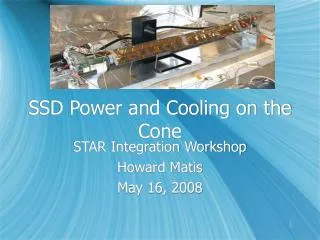
A New Proposal for Cooling the SSD. Jim Thomas Lawrence Berkeley National Laboratory 10/27/2008. The SSD is air cooled. Air In. P Side Electronics. 1 cm Orifice. P Side Electronics. Air Out. Philosophy.

E N D
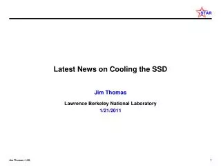
A New Proposal for Cooling the SSD Jim Thomas Lawrence Berkeley National Laboratory 10/27/2008
The SSD is air cooled Air In P Side Electronics 1 cm Orifice P Side Electronics Air Out
Philosophy • The performance of the old electronics was perfectly satisfactory when the cooling system was in perfect condition • 6 out of 20 ladders have always performed well • The new SSD electronics will be designed with ‘next generation’ components • The new electronics is projected to consume less power than the old electronics even though the new electronics is faster • So if we can design a new cooling system that has the same cooling capacity as the old system, but is more reliable, then we should be successful in cooling the new electronics, too. Reduce the problem to one that has already been solved
Heat Load – old electronics on ladder #0 Total Consumption: 16 Watts per Ladder
Requirements • 16 W per ladder (some documents casually say 20 W (?)) • 20 ladders (and 4 RDO boxes) cooled by a system that pulled the air across the ladders (i.e. vacuum) • Cross sectional area of each ladder (near Si wafers) is ~ 20 cm2 • Thus a flow rate of 1 liter / sec requires an air speed of 0.5 m/sec • 16 Joules into 1 liter of air requires a T of 12 degrees K • Heat capacity of lab air is 0.0013 J / cm3 / K 1 l/sec of air at 0.5 m/sec was extensively tested on the bench, and was shown to work, without vibration or other difficulties
Performance of Cooling System on Ladder #0 Measurements confirm that the majority of heat from the ladder is transferred to the cooling air stream. Temperature (C) T 11 C Time (hours)
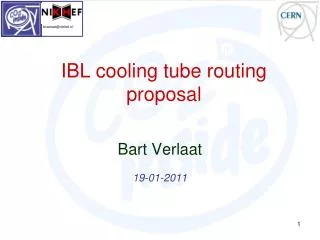
The Previous Solution – a VortecTransvector The previous solution was compact, convenient and clever The left panel (above) shows the vacuum distribution manifold that transfers air from the small diameter tubes to the Transvector. The right panel shows the Transvector airflow amplifier and its principles of operation. It worked. The Transvector drew air over the ladder by starting with air from the IFC (~1 bar). The system had a measured pressure drop of -12 mbar at the far end of the ladder and -43 mbar after 4.5 m of 8 mm (ID) plastic hose.
Vacuum Curve for the Vortec System • The operating point for the SSD is shown in red • Red diamond is for one Transvector = (5 ladders + 1 RDO) • The TransvectorVortec air flow amplifier is perfectly matched to the SSD operating conditions • Red circle is the sum of 4 Transvectors = (20 ladders + 4 RDOs) • However, the curves are very flat and so there is not really any excess capacity in case of a kinked hose and no ability to raise the airflow by 20% (as may be desired). Model 903 Model 902
A Different Solution to the Same Problem • The wood products industry needs high volume vacuum sources to clear wood chips from around saws and lathes. • Thus, there is a commercial line of vacuum sources that provide vacuum with more flow and pressure than we need. • These vacuum sources can be purchased, off the shelf, and are designed for continuous operation. They run on 3 phase 240 VAC. http://www.dustcollectorsource.com/
RP-212-EL and RP-426-QL • A wide variety of option are available. Shown above are the vacuum curves for a 1.2 kW and a 2.6 kW system from a small company in Southern California. • They will build to suit our needs. Cost is about $4K. • Either system is more than sufficient for the needs of the SSD and gives a convenient amount of excess capacity to enable us to keep the motor cool and even increase the airflow, if necessary.
Losses are a function of distance • The vacuum source will be mounted on the North Platform • Dirty power available • We will need approximately 30 meters (100 feet) of tubing to run between the source and the manifold on the face of the TPC. • Using the old manifold is reasonable and desirable • The vacuum source is manufactured with 2 inch input ports • The pressure lost in a perfectly smooth tube that is 100 feet long is approximately 4 inches of water. http://www.gates.com/industrial/pressure/airFlow.cfm • However, the pressure lost in a 3 inch tube is only 0.5 inches of H2O • The only caveat on running a long plastic tube is to provide a conductor inside the tube to dissipate static charge • The pressure lost in a 8 mm (ID) tube that is 4.5 m (15 foot) long is 17 inches of water (43 mbar) • In good agreement with measurements • Note that a 1 cm (ID) tube only looses 13 mbar … very sensitive to ID We should use large tubes to conduct the vacuum. We are still limited by the 1 cm orifice on the ladders but we can tolerate this (and other small diameter hardware) by keeping the overall length of these sections very short.
Summary • Satisfactory cooling can be achieved by using a vacuum source to pull air from the IFC across the ladders of the SSD • Extensive measurements show that it works when everything is working perfectly • In order to achieve excess capacity to compensate for non-ideal conditions, we should go to a new source of vacuum • 230 V / 3 Phase Siemens turbine. The motors are brushless and rated for continuous operation, 25 year lifetime, 65 dBA. • We should use larger diameter hoses at each stage of the design • The most sensitive hoses are the ~ 1 cm diameter hoses between the manifold and each ladder. These can be made larger for the majority of the distance between the manifold and the SSD. • The ~ 1 cm hoses should be made stiff (so they won’t kink)
JT Notes and Homework • Do we have 230 Volt / 3 phase power on the N Platform? • Find source of connection hardware to manifold and ladders. These are less than 1 cm ID but we can and probably should continue to use them because they were chosen very wisely to help navigate the tricky twists and bends that occur at the ladders and near the manifold. This hardware should not be a serious problem as long as we connect to larger diameter tube and keep the small diameter sections very short. • Buy the parts and pieces and test the system.