Download
1 / 20
200 likes | 292 Views
Pilot Equipment Familiarization and Scenario Overview. Measures and Models of Aviation Display Clutter. [ Year 2 Experiment ]. June, 2008 NASA LaRC | NC State University | APTIMA. Experiment Setup - Aircraft Familiarization -. Simulator with Head-up Display. Integration Flight Deck:

E N D
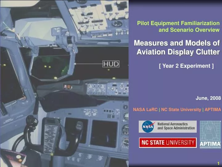
Pilot Equipment Familiarization and Scenario Overview Measures and Models of Aviation Display Clutter [ Year 2 Experiment ] June, 2008 NASA LaRC | NC State University | APTIMA
Simulator with Head-up Display • Integration Flight Deck: • No motion, ground-based Simulator • Replicating forward Flight Deck of Boeing 757 • HUD with new display features: • Two instrumentation modes – PRIM (primary mode symbology) & IMC symbology • Enhanced Vision System (EVS) • Synthetic Vision System (SVS) • Flight pathway guidance (TUNNEL) IFD Simulator
Tunnel • “Crow’s feet” define vertical and horizontal extent of desired path • 600 ft wide by 350 ft tall: • +/- 1 “dot” on path deviation indicators • “Linear” Deviation • Segments every 0.2 nm • Showing path 1 nm ahead
Flight Path Marker As speed increases relative to selected speed, “worm” increases in size Appears below flight path marker when decelerating
Full-Scale Localizer Deviation Path Deviation Indicators • Vertical and lateral deviation path deviation indicators: • Deviation scale • Center, +/-2 Dots • Pathway deviation indicator • “Dogbones” • Derived from navigation solution / “Synthetic Vision System” • ILS deviation indicator • Glideslope and localizer deviation • No “Bends” • No “Lies” • “Raw Data”
Runway Outline (under 500 feet) • Glideslope Reference Line (GSRL) • Set at 3.1 degree • Used for Flight Path Reference under 500 ft. Note: At 75 ft. above the runway, flare cues will emerge from the bottom of the display.
IMC / Tunnel / SVS Configuration Wireframe rendering of terrain model (based on GPS database)
PRIM / EVS Configuration Shaded rendering of FLIR (Forward-looking Infra-Red Radar) When flying in clouds with the EVS “on”, FLIR returns on water vapor may create “ghost”-like images on HUD
Flight Scenario Overview • KRNO ILS RWY 16R Final: • Hand-flown with manual throttles • Begins on localizer abeam PYRAM • Ends with landing or missed approach decision • Night/IMC: • Weather near or below minimums • Crosswinds with no gusts • Go-around or landing performance will not actually be measured
Aircraft Configuration and Operation • Autopilot and autothrottles inoperative • PFDs and NDs inoperative • All NAVAIDs set for approach • FMC inoperative • FD inoperative • Landing and wing lights “off” in clouds. • Can activate lights on breakout.
Roles and Responsibilities • Captain • Hand flying • Verbalize all decisions at published minimums and EVS mins. • Call for gear, flaps, etc. as desired. • First Officer (FO) • Handle ATC communication • Actuate gear and flaps on command • Set airspeed and altitude bugs • Complete checklists • Provide callouts as briefed (altitude) • Will confirm objects in sight (visually) • Will answer queries and confirm settings, procedures, etc.
Standard Approach Procedures • Initial Approach • 210 KIAS • Gear and flaps retracted • Below 210 KIAS • Flaps 15 degrees • Landing gear extended • Below 162 KIAS • Flaps 30 degrees • Landing gear extended • Before landing checklist • Approach Speed • 138 KIAS for all landings
Approach Procedures (cont.) • Standard Rules (without EVS) • Runway must be visible with naked eye from published decision height • EVS Rules • Published decision height: • Runway must be visible with EVS • Continue to 100 HAT (Height Above Touch-down), if EVS shows approach lights, threshold, or touchdown zone. • FAR 91.175c - For straight-in instrument approach procedures…the pilot [must] determine that the enhanced flight visibility observed by use of a certified enhanced flight vision system is not less than the visibility prescribed in the standard instrument approach procedure being used. • 100 HAT • Runway must be visible with naked eye • Land only if threshold or touchdown zone visible