Download
1 / 37
380 likes | 541 Views
Stabilizing the Carrier-Envelope Phase of the Kansas Light Source. Eric Moon Zuoliang Duan 11-9-2005. Outline. Theoretical Description of the CE phase Why do we care about the CE phase? Can we control it? Yes! Here’s how it’s done for the KLS and why it works.

E N D
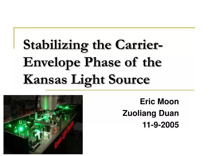
Stabilizing the Carrier-Envelope Phase of the Kansas Light Source Eric Moon Zuoliang Duan 11-9-2005
Outline • Theoretical Description of the CE phase • Why do we care about the CE phase? • Can we control it? Yes! Here’s how it’s done for the KLS and why it works. • Single-Shot CE Phase Measurement Setup • Results • Future Plans
Why do we care about controlling the change of the carrier-envelope phase? • Important for experiments utilizing few-cycle laser pulses, e.g. High Harmonic Generation • Can use a stabilized frequency comb to perform spectroscopy. • Related to this year’s Nobel prize! • More applications to come!
Results from Others • Fortier et al1, have reported phase coherence times of 326 s. • Witte et al2, have observed coherence times of 500 s. • Our group has observed coherence times of 85 s. • The main goal is to achieve long term, on the order of hours, for running experiments. [1] Fortier et al, IEEE Journal Topics Quantum Electron, Vol. 9, 1002-1010, 2003 [2] Witte et al, App. Physics B, 78, 5-12, 2004
Theory1 Mode-locked lasers emit a regular train of pulses. For a single laser pulse: Envelope-function Carrier-frequency Carrier-envelope phase [1] Fortier et al, IEEE J. Select. Topics Quantum Electron., vol. 9, pp.1002-1010,2003.
Theory1 Time-Domain Description of the Mode-Locked Pulse Train [1] Fortier et al, IEEE J. Select. Topics Quantum Electron., vol. 9, pp.1002-1010,2003.
Theory1 Due to material dispersion inside the laser cavity, the CE phase changes. The laser cavity length: [1] Fortier et al, IEEE J. Select. Topics Quantum Electron., vol. 9, pp.1002-1010,2003.
Theory1 Mode-Locked Pulse Train in the Time Domain: Mode-Locked Pulse Train in the Frequency Domain: [1] Fortier et al, IEEE J. Select. Topics Quantum Electron., vol. 9, pp.1002-1010,2003.
Frequency Comb and Laser Spectrum1 [1] Fortier et al, IEEE J. Select. Topics Quantum Electron., vol. 9, pp.1002-1010,2003.
Theory The regular spacing of the frequency comb allows access to the change of the carrier-envelope phase. How? Can use a self-referencing technique!
Theory1 The self-referencing technique requires an octave-spanning spectrum of the laser. Beating the second harmonic and fundamental frequency combs of the laser yields a frequency proportional to the change of the carrier-envelope phase. [1] Fortier et al, IEEE J. Select. Topics Quantum Electron., vol. 9, pp.1002-1010,2003.
Theory • The CE phase change can be controlled by locking the offset frequency, f0, to a known frequency. • In the case of the KLS, f0 is set equal to one-quarter of the repetition rate of the oscillator.
Experiment • The KLS utilizes a Kerr-Lens Mode locked Ti:Sapphire Oscillator emitting a ~77 million pulses per second. • The pulses are roughly 12 fs at the output of the laser and carry nJ energy per pulse. • The oscillator is the starting point for the self-referencing technique.
Why not use the amplifier output? One reason: Spectrum too narrow!
KLS Oscillator Cavity Pump M5 Lens A1 Ti:S M1 ECDC-Module M0 M6 M7 CP M9 M3 OC M8 M2 M10 M4E Ultrashort Pulse Output M4
Stabilization Experimental Setup offset frequency photodiode APD collimating Lens f=30mm focusing Lens f=30mm focusing Lens f=30mm HR1064nm mirror HR532nm mirror BBO crystal λ/2 half wave plate 1064nm polarizing beam-splitter 532nm filter RG715 HR532nm mirror λ/2 half wave plate 532nm λ/2 HR532nm mirror half wave plate 532nm dichroic beam splitter HR 532nm,HT1064nm polarizing beam-splitter 532nm out-coupling objective f=8.55mm in-coupling objective f=7.5mm IR mirror Silver mirror PCF λ/2 half wave plate 800nm Chirped mirror Chirped mirror grating 900lines/mm From fs Laser
532 nm 1064 nm
Observation of Beat Note and Frequency Comb frep-f0 f0=19.375MHz
CE Phase Stability After Pulse Amplification2 • A second f-2f interferometer after the KLS amplifier provides a means for quantifying the CE phase stabilization stability. • 10% of the KLS amplifier output is sent to the experimental setup. • White-light is generated in a sapphire plate and a BBO crystal provides second-harmonic generation. • [2] Baltuska et al.,IEEE J. Select. Topics Quantum Electron., vol. 9, pp. 972-989, 2003.
Theory2 Interference between the white light and second harmonic pulses: Phase of the Interference Signal: The shot-to-shot change of this phase can be monitored by the second f-2f setup. • [2] Baltuska et al.,IEEE J. Select. Topics Quantum Electron., vol. 9, pp. 972-989, 2003.
Experiment locking electronics Pump AO modulator M5 Lens A1 Ti:S M1 M0 M6 M7 HR IR mirror BS 50:50 CP M3 OC M8 M2 M4E M4 nonlinear interferometer spectral broadening HR IR mirror BS 9:1 stretcher compressor amplifier 1kHz fs laser HR IR mirror Single-shot phase measurement
f-2f Interferometer after KLS Amplifier 1kHz fs laser concave silver Mirrors: f=100mm half wave plate half wave plate spectrometer FCWL two silver mirrors SHG VNA VNA sapphire d=2.3mm FCWL: fundamental Continuum white light silver mirrors silver mirror polarizer BBO f=70mm ∆T=0.265ps SHG FCWL 532nm HR mirror 532nm HR mirror f=75mm
Spectrum of the Second Harmonic generated in the BBO Crystal
1 pulse Phase-Locked Not Phase-Locked
51 pulses Phase-Locked Not Phase-Locked
101 pulses Phase-Locked Not Phase-Locked
200 pulses Phase-Locked Not Phase-Locked
1000 pulses Phase-Locked 10000 pulses phase-locked 103000 pulses Phase-locked
Summary • The change of the carrier-envelope phase of the KLS has been stabilized. • A technique for observing the carrier-envelope phase change shot-to-shot has been utilized. • CE phase coherence times of up to 85 seconds have been observed.
Future • Send a slow CE phase drift signal from the second f-2f interferometer back to the locking electronics to achieve longer locking times.
Thanks! • Dr. Zenghu Chang • Al Rankin • KLS Members: Mahendra Shakya, Shambhu Ghimire, Chris Nakamura, Chengquan Li, and Steve Gilbertson • Zuoliang Duan for being a great partner on this project. • Dr. Corwin and Dr. Washburn