Download
1 / 64
650 likes | 848 Views
Paths and Circuits. Lecture 52 Section 11.2 Wed, Apr 26, 2006. The Seven Bridges of K ö nigsberg. In the city of K ö nigsberg, two branches of the Pregel River came together, with an island at their junction. The Seven Bridges of K ö nigsberg.

E N D
Paths and Circuits Lecture 52 Section 11.2 Wed, Apr 26, 2006
The Seven Bridges of Königsberg • In the city of Königsberg, two branches of the Pregel River came together, with an island at their junction.
The Seven Bridges of Königsberg • There were seven bridges crossing the river at various places.
The Seven Bridges of Königsberg • The challenge was to start at one point, cross each bridge exactly once, and return to the starting point. ?
Euler’s Solution • Euler abstracted the bridges as a graph with four vertices and seven edges.
North Shore Peninsula Island South Shore Euler’s Solution • Each vertex represents a land mass and each edge represents a bridge.
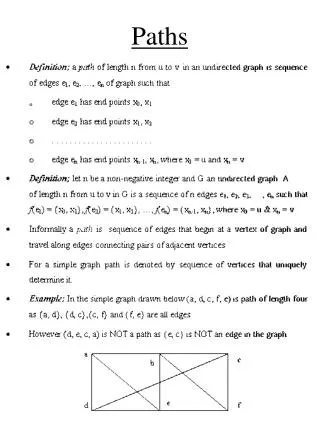
Walks and Paths • A walk from vertex v to vertex w is a finite alternating sequence of adjacent vertices and edges from v to w: v0e1v1e2 … en – 1vn – 1envn, where v0 = v and vn = w. • A path from v to w is a walk that does not repeat any edge.
Walks and Paths • A simple path is a path that does not repeat any vertices. • A closed walk is a walk that starts and ends at the same vertex. • A circuit is a closed path. • A simple circuit is a circuit that does not repeat any vertex.
Synopsis • walk = from A to B, no restrictions. • path = walk, no repeated edge. • closed = from A to A. • circuit = closed walk. • simple = no repeated vertex.
Euler Circuits • An Euler circuit is a circuit that contains every vertex and every edge of the graph. • The problem of the Seven Bridges of Königsberg is to find an Euler circuit.
Connected Graphs • A graph is connected if, for every pair of vertices v and w, there is a walk from v to w. • A connected component of a graph is a maximal connected subgraph.
Euler’s Solution • Theorem: A graph has an Euler circuit if and only if it is connected and every vertex has even degree. • Thus, an Euler circuit over the Seven Bridges of Königsberg does not exist.
King’s Dominion I-95 RMC The Two Bridges of Ashland • At Randolph-Macon College, they have been trying to solve the Two Bridges of Ashland problem for decades. ?
Proof • Proof (): • Suppose a graph G has an Euler circuit. • Let v V(G). • Then as we travel the circuit, each time we pass through v, we “use up” two of the edges incident to v. • When we finish the circuit, we have used all the edges incident to v.
Proof • Thus, v had an even number of edges. • Obviously, G must be connected.
Proof • Proof (): • Now suppose that G is connected and that every vertex of G has even degree. • Choose a vertex v at which to begin. • deg(v) > 0 since G is connected, so follow one of the edges incident to v. • Let w be the next vertex. • We used one of w’s edges to get there.
Proof • w has even degree, so there is at least one more edge available that we can follow. • This happens at every vertex that we visit. • Thus, the circuit is forced to terminate only when we return to the starting vertex v. • This procedure alone does not necessarily produce an Euler circuit.
Proof • Suppose there are edges that were not used. • Follow the original circuit until a vertex is reached that is incident to one of the unused edges. • Apply the original procedure to produce a circuit that starts and ends at this vertex. • “Splice” it into the original circuit.
Proof • Continue in this way, splicing circuits into the existing circuit, until there are no unused edges remaining. • The result is an Euler circuit.