Download
1 / 25
280 likes | 890 Views
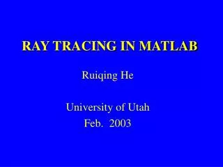
RAY TRACING IN MATLAB. Ruiqing He University of Utah Feb. 2003. Outline. Introduction Modeling Strategy and steps Reflection and multiple ray tracing Examples Conclusion. Introduction. Role of ray tracing in geophysics Practical requirements: accuracy, speed, ray path ,

E N D
RAY TRACING IN MATLAB Ruiqing He University of Utah Feb. 2003
Outline • Introduction • Modeling • Strategy and steps • Reflection and multiple ray tracing • Examples • Conclusion
Introduction • Role of ray tracing in geophysics • Practical requirements: accuracy, speed, ray path, reflection, multiples, 3D,amplitude. • Matlab
Ray Tracing Methods • Shortest path methods: Fischer (1993), Moser (1991) • Wave-equation-based: Sava (2001)
This Ray Tracer • Shortest path method: Grid of velocity is finer than or equal to the grid of ray path. • Versatile: reflection & multiples • Accurate • Robust
Modeling • Block model & grid model
Strategy • Fermat’s principle • Huygen’s principle: original source and secondary source • Data structure: V(x,z), T(x,z), Ray(x,z,1:2) • Flag(x,z): 0-unvisited; 1-visited; 2-decided
Steps • Step 0: T(x0,z0)=0; Flag(x0,z0)=2; Ray(x0,z0,1)=x0; Ray(x0,z0,2)=z0; • Step 1: sub-ray tracing from the original source.
Search • Step 2: all visited nodes record: T(x,z) and Ray(x,z,1:2), Flag(x,z)=1. • Step 3: search nodes Flag(x,z)==1 & min(T(x,z)). • Step 4: decided node = next secondary source, as original source, repeat from step 0, until all interested nodes are decided.
Reflections and Multiples • Step 1: do one transmission ray tracing until all nodes on the reflector are decided. • Step 2: keep these nodes and make them Flag=1, refresh all other nodes. • Step 3: jump directly into step 3 in the transmission ray tracing loop. So, 1 reflection ray tracing = 2 transmission ray tracing; 1 first order multiple ray tracing = 4 transmission ray tracing; 1 2nd order multiple ray tracing = 6 transmission ray tracing;
Reflections and Multiples Frozen exploding reflector
Examples • Linear gradient model Travel time field Sec. 0.08 0.05 50 m 0 100 m 50 m 100 m
Comparison 0.09 s T 0.07 s 75 m 95 m Distance
Ray path 50 m 100 m 100 m 50 m
Reflection ray tracing 50 m 100 m 50 m 100 m
Multiple ray tracing 50 m 100 m 50 m 100 m
Complex model ray tracing Salt Dome Model ft/s 14000 6000 ft 6000 12000 ft 25000 ft 50000 ft
Travel Time Field Sec. 5 3 6000 ft 12000 ft 0 25000 ft 50000 ft
Ray Path 6000 ft 12000 ft 25000 ft 50000 ft
Speed CPU Time on a 2.2 GHZ AMD CPU Time (Sec.) 16 10 2 40,000 90,000 10,000 Grid size
Conclusion • Flexibility: ray path, reflections & multiples • Speed: depends on sub ray tracing length • Accuracy and robustness • Applications: tomography and migration • Extendable: C or Fortran • Available by email: rhe@mines.utah.edu
Thanks • 2002 members of UTAM for financial support.