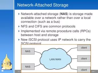
Attached-Culture Systems
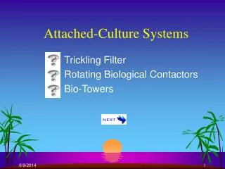
Attached-Culture Systems. Trickling Filter Rotating Biological Contactors Bio-Towers. Trickling Filter.

Attached-Culture Systems
E N D
Presentation Transcript
Attached-Culture Systems Trickling Filter Rotating Biological Contactors Bio-Towers
Trickling Filter Biofilm or bacterial film or biomass is grown or developed on solid medium. Such as rocks, stone trieces, synthetic medium etc. This media is randomly pocked in reactor. Wastewater is applied on the top through a rotating arm and it trickles down of the bottom. In its travel to the bottom of TF, wastewater is brought into the centure of biofilm attached to the medium. The process may be depicted as shown below.
How does it work? O2 and Nutrients (BOD etc ) are transferred to the fixed film by diffusion Oxidized organics are transferred to moving after layers by diffusion.
Continue…..How does it work? • Bacteria metabiological contents of the fixed film. • Biofilm grows or get thickened. • As it’s thickness increases, inner layer become anaerobic.
Continue…..How does it work? • Outer biolayer remains aerobic. • With more thickining of biological layer , cells in inner layer die and lyses It causes break in the content between film and medias.
Continue…..How does it work? Thus, slim layer gets slough off and is being carried away by the wastewater. In SST, biofilm material (----- half) is separated.
Parameter Low Rate Filter (LRF) Intermediate Rate Filter (IRF) High rate Filter (HRF) H--- Hydraulic loading m3/m2 -d 1 – 4 4 – 10 10 – 40 Uol. loading kg/m3 – d 0.08 – 0.32 0.28 – 0.48 0.32 – 1.0 Depth, m 1.5 –3.0 1.25 – 2.5 1.0 – 2.0 Recirculation Ratio 0 0 – 1 1 – 3 Power Requirements kw/103 m3 2 – 4 2 – 8 6 – 10 Each area ------- the does at least at 5 min ntervals.
Design of Trickling filters: Generally Empirical Formula: • NRC Formula S0 Incoming BOD Se Effluent BOD Q Flow in m3 / min Volume of filter in m3 r Recirculation ratio F Recirculation Factor,
For the second stage 1.Volume of media 2.No. of stages 3.Recirculation Ratio
Eckenfelder Formula: Account for media characteristics, PFR, First order kinetics (i) No Ricirculation: K = Treatability constant, min-1(0.01 – 0.1 ) D = Depth, in m Domestic –0.06 at 200c N = Coefficient, characteristic of medium (0.35 – 0.80) rock = 0.408 asbestos = 0.75 Q = m3 / m2 – min KT = K20 (1.035) T – 20
Additional notes on Trickling Filter: Sludge in Trickling Filter: • Sludge in TF = 100 day (long c endogeous decay, low X, more stablised Sludge) • Actual Biomass is difficult to analyse • Overall yield coefficient is 60 – 80% of AST Process • High rate TF produce more Sludge
Air Supply in TF: • Natural draft : Temperature difference in air & wastewater IIf wastewater temp. < Ambient temp. : downward flow of air , If Wastewater Temp. > Ambient Temp. : Upward Flow of Air. • Under drains & collecting systems should be designed to flow no more than half to allow force air passing • 1 m2 for every 250 m2 of filter area
Hydraulics of Trickling Filter: ØRotating arm: ½ - 2 rpm ØPeripheral Speed: 0.5 – 3.7 m/min (two arm system) ØArm length : 4.5 – 70m ØPorts : 95mm in dia. Ø15cm above media. ØFlow velocity in arms > 0.3 – 0.6 m/s to prevent deposition of particulates ØSize of parts is generally same.
Spacing : Step discharge -----graph-------- ØArea serviced increases square of the distance from the center of the filter. For even distribution of flow over filter: Flow rate in area ------image------- Ql (flow in pipe at l ) =
1. Draw Q versus l, get spacing 2. Determine q for each part & h near--- spacing.
Application of Trickling Filter Onsite Treatment House Hold