The MECO Muon Beam: Lepton Flavor Violation Search and Experimental Summary
This presentation outlines the MECO (Muon to Electron Conversion) experiment, which aims to investigate lepton flavor violation (LFV) in the charged sector. Conducted by a collaboration of institutions including the University of California, Irvine, and Brookhaven National Laboratory, the MECO experiment seeks to detect coherent conversion of muons to electrons with an unprecedented sensitivity below (2 times 10^{-17}). Topics covered include the physics motivation, requirements for proton and muon beams, expected performance, backgrounds, and beam dynamics crucial for maximizing muon luminosity.

The MECO Muon Beam: Lepton Flavor Violation Search and Experimental Summary
E N D
Presentation Transcript
The MECO Muon Beam Michael Hebert University of California, Irvine Snowmass Particle Sources (T4) Session July 16, 2001 M. Hebert, UCI The MECO Muon Beam
Muon to Electron COnversion (MECO) Collaboration Boston University J. Miller, B. L. Roberts, O. Rind Brookhaven National Laboratory K. Brown, M. Brennan, L. Jia, W. Marciano, W. Morse, Y. Semertzidis, P. Yamin University of California, Irvine M. Hebert, T. J. Liu, W. Molzon, J. Popp, V. Tumakov University of Houston E. V. Hungerford, K. A. Lan, B. W. Mayes, L. S. Pinsky, J. Wilson University of Massachusetts, Amherst K. Kumar • Institute for Nuclear Research, Moscow • V. M. Lobashev, V. Matushka, A. N. Toropin • New York University • R. M. Djilkibaev, A. Mincer, • P. Nemethy, J. Sculli • University of Pennsylvania • W. Wales • Syracuse University • R. Holmes, P. Souder • College of William and Mary • M. Eckhause, J. Kane, R. Welsh M. Hebert, UCI The MECO Muon Beam
Outline • Physics Motivation for MECO • Requirements on the Proton and Muon Beams • AGS and Extraction Beamline Modifications • The MECO Apparatus • Expected Performance • Current Status and Schedule • Summary M. Hebert, UCI The MECO Muon Beam
lmd led MECO is a Lepton Flavor Violation Search • Generation Number isnearly conserved • Experimental evidence indicates that conserved additive quantum numbers are associated with each lepton generation • No known gauge symmetry is responsible for this conservation • Observation of LFV in the charged sector is an unambiguous signal of physics beyond the Standard Model • In the Standard Model (SM) conservation is exact for degenerate n masses • LFV can occur for non-degenerate masses via n mixing loop diagrams in an extended SM, but this contribution to charged sector LFV rates is many orders below experimental reach • Nearly all models beyond the SM allow LFV at MECO accessible rates • Effective mass reach of sensitive searches is enormous • M. Hebert, UCI The MECO Muon Beam
Evolution of LFV Sensitivity & MECO Goal • Lepton Flavor Violation search sensitivity by year and channel • MECO goal is to detect coherent mN eN conversion with a single event sensitivity < 2 10-17 Figure courtesy Yoshi Kuno Expected MECO Sensitivity M. Hebert, UCI The MECO Muon Beam
MECO’s Signal • Muons are brought to rest in thin target foils where they form muonic atoms in the 1s state, resulting in one of the following; • Nuclear capture: • Muon decay in orbit: The Primary Background • Conversion: The Signal • The signal is easy to detect in principle - a single 105 MeV/c electron • MECO sensitivity is directly proportional to total number of stopped muons thus maximizing the integrated muon luminosity in the appropriate energy range is the primary goal of the MECO muon beam M. Hebert, UCI The MECO Muon Beam
Generating the High Intensity Muon Beam • Use the AGS as the high intensity proton driver operating at 8 GeV • Much larger fraction of useable muons than ~1 GeV beams produce • Below AGS transition • Near enough to production threshold to limit that background contribution • 1000 fold increase in muon intensity using an idea from MELC at MMF • High Z target for improved pion production • Graded solenoidal field to maximize pion capture Reflected m p Proton Beam Bz z M. Hebert, UCI The MECO Muon Beam
Backgrounds • Muon Decay in Orbit – The limiting background • Emax = energy of electron from • dN/dEe (Emax – Ee)5 • Sets requirement for electron energy resolution of the detector system • Radiative Muon Capture: • Egmax = 102.5 MeV/c2, P(Eg > 100.5 MeV/c2) = 4 10-9 • P(g e+e-, Ee-> 100.5 MeV/c2) = 2.5 10-5 • Electron energy resolution required to minimize #1 above eliminates this • Radiative Pion Capture: • Branching fraction ~ 1.2% for Eg > 105 MeV/c2 • P(g e+e-, 103.5 < Ee-< 100.5 MeV/c2) = 3.5 10-5 • Requires p-/p ratio at stopping target is < 10-15 when the detector is active • Addressed in MECO with pulsed proton beam M. Hebert, UCI The MECO Muon Beam
Backgrounds • Muon Decay in Flight + e- Scattering in Stopping Target • Again prompt background eliminated with a pulsed beam • Beam e- Scattering in Stopping Target • Requires e-/p ratio at stopping target is < 10-7when the detector is active • Eliminated using pulsed beam • Antiproton Induced e- • Propagate slowly such that late backgrounds can be generated • Requires thin absorber to stop antiprotons in muon transport line • Cosmic Ray Induced e- • Primarily muon decay and interactions • Scales with running time, not beam luminosity • Requires the addition of active and passive shielding M. Hebert, UCI The MECO Muon Beam
Background Elimination Beam Requirements • Pulsed beam to eliminate prompt backgrounds following PSI method (A. Badertscher, et al. 1981) • Beam pulse duration << tm to allow for the maximum usable time window • Pulse separation tm • Extinction between pulses < 10-9 • Limit the secondary beam to muons of the appropriate charge and optimal stopping momentum as much as possible • Thin antiproton absorber to eliminate late backgrounds from slowly drifting • No direct line-of-sight between muon production target and stopping target to prevent neutrals interacting in the stopping target • Separate muon beam and proton beam as much as possible M. Hebert, UCI The MECO Muon Beam
AGS Beam Requirements for MECO • AGS Revolution time = 2.7 ms (nominally with 6 RF buckets) • Fill 2 RF buckets at 180for 1.35 ms pulse spacing with 20 x 1012 (Tp) each • Slowly extracted (0.5 s) in < 50 ns wide bunches • Inter-bunch extinction ratio 1:109 or better M. Hebert, UCI The MECO Muon Beam
Bunch Intensity • AGS is filled from the Booster flexibility in filling isolated buckets • Evolution of bunch numbers: • One-bunch mode in the Booster is preferred but intensity is an outstanding question M. Hebert, UCI The MECO Muon Beam
AGS Intensity • Total intensity (40 Tp) is modest by AGS standards manageable beam loading • The present per-bunch intensity limit comprises • Space charge effects during accumulation, 800 ms nominally 133 ms (one Booster cycle) for MECO • Momentum aperture constriction at transition prevents use of full longitudinal acceptance of AGS MECO running below transition removes this constraint • Machine studies are required to achieve the appropriate optimum for this new, less constrained regime M. Hebert, UCI The MECO Muon Beam
Bunched Extraction Concept • Slow resonant extraction with RF on (60 ns bunches) • RF accelerates the beam into extraction resonance • A small slice of phase space is peeled off from the bunch M. Hebert, UCI The MECO Muon Beam
Extinction Measurements • Initial test at 24 GeV with one bucket in the AGS yielded <10-6 extinction between buckets and 10-3 in unfilled buckets • A second test at 7.4 GeV with a single bucket found <10-7 extinction • Test time was insufficient in either case to optimize the extinction during the test • It is possible that careful tuning alone will suffice to achieve <10-9 but we are conservatively assuming that it will not M. Hebert, UCI The MECO Muon Beam
Belt and Suspenders Extinction Enhancement • AGS Internal Hardware Additions • AC Dipole Magnet and Kicker system • RF modulated dipole and Lambertson magnets in proton transport line • Trap what the internal cleanup misses • Monitor the effectiveness of the internal system M. Hebert, UCI The MECO Muon Beam
AGS Inter-Bunch Cleanup • Principle: Excite coherent vertical betatron resonance, but only for beam outside the bunch • Hardware: ACdipole at 80 kHz + fast (100 ns) kickers to cancel dipole field for filled bunches Proton Bunches AC Dipole Signal Fast Kicker Signal 2 ms M. Hebert, UCI The MECO Muon Beam
FY98 Test Results AC Dipole drives beam out of the machine in 20 ms AC Dipole 10 ms Kicker Kicker restores beam (note that it is too weak to do so completely) AC Dipole (lower voltage) M. Hebert, UCI The MECO Muon Beam
Proton Beamline Extinction Cleanup • RF Modulated Dipole + Lambertson Magnets • Filled buckets • Arrival at RF dipole coincides with maximum field in the dipole • Beam is deflected into shielded channels in Lambertsons • Beam arriving out-of-time • Receives less than maximal deflection in dipole • Enters diversion channel in Lambertsons • Counter placed after sufficient drift space downstream of the Lambertsons serves as a monitor of AGS internal extinction • Counter viewing a secondary target foil downstream of the production target serves to monitor total extinction performance by integrating over many pulses M. Hebert, UCI The MECO Muon Beam
Proton Beamline – Upstream External Kicker Pitching Magnet Lambertsons M. Hebert, UCI The MECO Muon Beam
Proton Beamline – Downstream Production Target Pitching Magnet Proton Beam Dump M. Hebert, UCI The MECO Muon Beam
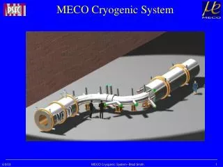
The MECO Apparatus Muon Beam Stop Straw Tracker Muon Stopping Target Superconducting Transport Solenoid (2.5 T – 2.1 T) Crystal Calorimeter Superconducting Production Solenoid (5.0 T – 2.5 T) Superconducting Detector Solenoid (2.0 T – 1.0 T) Collimators Muon Production Target Proton Beam Heat & Radiation Shield M. Hebert, UCI The MECO Muon Beam
Production Solenoid • Requirements • Capture low energy p produced in the target and to direct them to the transport solenoid • Operate in the radiation environment from 50 kW p beam interacting in target • Implementation • 5 T field at upstream end, axially graded to 2.5 T at the transition to the transport solenoid • 1.5 m diameter clear bore allowing 45-55 cm thick Cu and W shield, 40-60 cm dia. clear area M. Hebert, UCI The MECO Muon Beam
Production Target • Currently a radiation cooled Tungsten rod with high emissivity coating • 16 cm in total length • 8 mm in diameter • Segmented into 40 - 80 pieces • Maximum temperature is ~2200K • Not a problem for melting (3600K+) or evaporation (2x10-12 gm/cm2s) • Pushes limits on stresses • Requires flat proton beam profile rather than the nominal gaussian profile rastered p beam or octopole magnet • Needs further thermal and stress analyses as well as prototyping • Water cooling is also under study M. Hebert, UCI The MECO Muon Beam
Muon Yield Studies • Muon flux estimate based upon measured pion data on Ta at 10 GeV (0 < q < 180 and Ep > 50 MeV) • MECO m and p flux simulated with GEISHA, FLUKA at 8 GeV • Simulation results scaled to match pion spectrum to data M. Hebert, UCI The MECO Muon Beam
Transport Solenoid • Requirements • Transport low energy m- from the production solenoid to the detector solenoid • Minimize transport of positive particles and high energy particles • Minimize transport of neutral particles • Absorb anti-protons in a thin window • Restrictions on dB/dz to minimize long transit time trajectories • Implementation • Curved magnet system to eliminate line of sight transport of neutral particles • Curved to drift positive particles and high momentum particles into collimators • Graded field with dB/dz < 0 Collimators M. Hebert, UCI The MECO Muon Beam
Effect of the Transport Solenoid • No line-of-sight for photons • Charge and momentum selection due to curvature drift • Positive particles heavily suppressed • High momentum negative particles suppressed M. Hebert, UCI The MECO Muon Beam
Detector Solenoid • Requirements • Graded field in front section to increase acceptance and reduce cosmic ray background • Uniform field in spectrometer region to minimize corrections in momentum analysis • Use of return yoke as part of the passive cosmic ray shield • Implementation • 1.9 m diameter bore, 10 m long, 2 T at entrance, 1 T in spectrometer • 0.2% uniformity in region of spectrometer • Serves as vacuum vessel for bore • Graded field with dB/dz < 0 Calorimeter Straw Tracking Detector Muon Stopping Target M. Hebert, UCI The MECO Muon Beam
End of the Line • Muon Stopping Target • 17 thin (0.2 mm) Al or Ti foils • In axially graded field region to collect conversion electrons similarly to pions in the production solenoid • Straw Tracker • 5 mm diameter, 2.5 m long straw tubes of carbon-loaded Kapton • Three layers of straws in each section/vane for redundancy and ambiguity resolution • Axial coordinate is determined by cathode pads on the exterior of the straws • Operates in vacuum • Calorimeter • Primary hardware trigger for the experiment • Additional constraints on electrons via energy and impact point matching with track M. Hebert, UCI The MECO Muon Beam
Expected Sensitivity & Background • Expect~ 5 signal events for107 s (28 weeks, 2800 hours) running if Rme = 10-16or equivalently a single event sensitivity of 2 10-17 • Expect ~ 0.45 background events in 107 s M. Hebert, UCI The MECO Muon Beam
Current Status • Conceptual Design of the system of solenoids is underway at MIT’s Plasma Science and Fusion Center • Nearing closure on field configuration • Work has begun on mechanical support design • Additional beam studies will continue at a low rate this year, ramping up rapidly with project start • Optimization of extraction below transition this year • Extensive studies of extinction once AGS internal cleanup hardware is in place (1 year) • Similar studies in the proton extraction line with the external cleanup hardware (2 years) • Prior to administration change, project start was expected in FY02 – FY03 project start remains a strong probability according to NSF • The goal remains to complete construction in early ’06 and begin production running late in that year with the world’s most intense muon beam! M. Hebert, UCI The MECO Muon Beam
Summary of MECO Beam Characteristics M. Hebert, UCI The MECO Muon Beam