Download
1 / 29
290 likes | 454 Views
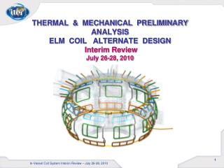
THERMAL & MECHANICAL PRELIMINARY ANALYSIS ELM COIL ALTERNATE DESIGN Interim Review July 26-28, 2010. In-Vessel Coil System Interim Review – July 26-28, 2010. Outline. BOUNDARY CONDITIONS NUCLEAR & RESTISTIVE HEAT GENERATION LORENTZ & PRESSURE LOADS

E N D
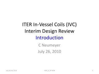
THERMAL & MECHANICAL PRELIMINARY ANALYSIS ELM COIL ALTERNATE DESIGNInterim ReviewJuly 26-28, 2010 In-Vessel Coil System Interim Review – July 26-28, 2010
Outline • BOUNDARY CONDITIONS • NUCLEAR & RESTISTIVE HEAT GENERATION • LORENTZ & PRESSURE LOADS • RADIATION ; CONDUCTION ; COOLING WATER @ 6 m/sec • MAGNESIUM OXIDE to COIL & JACKETS • STEADY STATE SANDWICH STRESS RESULTS : • THERMAL + PRESSURE LOAD RESULTS • THERMAL + PRESSURE + LORENTZ LOAD RESULTS • DESIGN IMPROVEMENT STRATEGIES • THERMAL + PRESSURE LOAD RESULTS • THERMAL + PRESSURE + LORENTZ LOAD RESULTS • SUB MODELING ; CORRECTION STRATEGY • CONCLUSIONS / PLAN: In-Vessel Coil System Interim Review – July 26-28, 2010
NUCLEAR HEAT GENERATION(W/M^3) 0.264 m The Poloidal Leg Applies a Similar Shaped Function The Toroidal Leg Nuclear Heat is Applied Based on a Curve fit of data from University of Wisconsin Team IVC Interim Design Review – 26-28 July 2010
IDEALIZED LOAD DIAGRAMS Thermal + Pressure + Lorentz Loading Load Thermal + Pressure Loading TRANSIENT STEADY STATE 30,000 Pulses Unknown Spectrum Time 5 hz Load 9,000 sec 3,000 sec Time
ELM LORENTZ LOAD VS POSITION Critical Quadrant (BOT) (BLC) (LFT) (TRC) (RHT) SECTOR #5 UNIT LOADS ARE MORE CRITICAL IN THE LOWER LEFT QUADRANT
SANDWICH DESIGNSection View No Hard Mechanical Attachment for tension Axial Translation Is Allowed DESIGN CONCEPT ALLOWS THERMAL DISPLACEMENT WITH SUPPORTS TO REACT LORENTZ LOAD IVC Interim Design Review – 26-28 July 2010
ELEMENT MESH Flexible Mounts To Facilitate Thermal Growth Symmetric Boundary Symmetric Boundary Rigid Boundary Rigid Boundary UNIFORM HEXAHEDRAL MESH
STEADY STATE TEMPERATURE ANALYSIS FULL OPERATING CONDITIONS Resistive Heat Generation Nuclear Heat Generation Cooling Water Applied
THERMAL BOUNDARY CONDITIONS Radiation Surfaces with View Factor =1 (dark blue surfaces) Nuclear HGEN Unspecified Surface Boundaries are conservatively assumed to be Adiabatic Temp in =105.7 C Temp out =131.5 C Conduction into Foundation at 100 C at all foundation interfaces The Copper Coil Temperature Distribution is an Equilibrium of all Combined Effects
RADIATION ASSUMPTIONS Incident Radiation is very small from 100 C Far Field All Form / View Factors equal to 1.0 Emissivity is a Hemispherical Average Across all wavelengths and directions IVC Interim Design Review – 26-28 July 2010
Steady State Temperatures With Heat Generation ; 6 m/s Water CoolingRadiation Max Temp = 476 C on Bracket TEMPERATURES ARE REASONABLE and WITHIN OPERATING LIMITS OF MATERIALS
Steady State Temperatures With Heat Generation ; 6 m/s Water CoolingRadiation Stainless Steel Jackets Max Temperatures ( 472 C = F) are within the limits of Stainless Steel With Cooling Water
Steady State Temperatures With Heat Generation ; 6 m/s Water CoolingRadiation Applied Boundary is: Temp in =105.7 C Temp out = 127.2 C Copper Coil shows net equilibrium of hottest leg 1.3 degrees higher than the Applied Boundary This trivial difference is explained by 1.) Initial Gap Contact conditions 2.) Number of elements through wall thickness 3.) Graphical Contouring of results 4.) Net equilibrium balance of all heat transfer effects The Coil Temperatures are Consistent with Hand Calculations and the Net Energy Balance of all Applied Thermal Loads
Steady State Fault Conditionwith Radiation Cooling Max Temperature Predicted on Surfaces that Exclude Radiation Fault Condition (No Water Cool or Resistive Heating) with Far Field Radiation Results in Temperatures that are within Material Capacity (316 SS Melt at 1375 C)
Steady State Fault Conditionwith Radiation Cooling Conservative Max Copper Temperature= 918 C Melting 1,078 C Fault Condition (No Water Cool or Resistive Heating) with Far Field Radiation Results in Temperatures that are within Material Capacity (CuCrZr Melt at 1,078 C)
STEADY STATE STRESS ANALYSIS THERMAL & DISRUPTION LOADS
Steady State Pressure + Thermal + Lorentz LoadSupport Reaction Loads RSYS 12 (Newtons) FX FY FZ 14038. -0.16031E+06 -19,761. . Poloidal +Z +Z Toroidal +Y +Y RSYS 14 (Newtons) FX FY FZ -36461. -0.11263E+06 13456 Typical Bracket Reaction Loads: FY =36,036 lbs is away from the Reactor on the Toroidal Bracket FY = 25,178 lbs is away from the Reactor on the Poloidal Bracket IVC Interim Design Review – 26-28 July 2010
Steady State Pressure + Thermal + Lorentz LoadDisplacements +Y 0.0066 m = 0.259 in +Y The Displacements are Reasonable for the Specified Boundary Conditions Lorentz Loads Acting Down Toward The Reactor
Steady State Mechanical + Thermal Loads + LorentzMax Principal Stress Restraint Location Stress shows: 1.) Bending across Restraints 2.) Exterior Jackets in Compression 3.) Interior Copper Coil in Tension Restraint Location The Stresses are Excessive However they are Manageable With the current strategies in progress
Steady State Mechanical + Thermal Loadsvon Mises Stress Copper Coil 0.450 e8 Pa = 6,526 Psi Copper Coil 0.185 e8 Pa = 2,683 Psi The Max Copper Coil Stress of 6.5 ksi will be Reduced with Bridge Support
Steady State Mechanical + Thermal Loads + Lorentzvon Mises Stress Max Copper Coil .184e9 Pa = 26,686 psi Copper Stresses Have Positive Limit Stress Margins and Negative Fatigue Margin Additional Section will be used to Redistribute These stresses
REVISED ANALYSISWith Bridge Support IVC Interim Design Review – 26-28 July 2010
Updated - Steady State Temperatures With Heat Generation ; 6 m/s Water CoolingRadiation Revised Plan July 22, 2010 Inlet Temp 70 C Outlet Temp 120 C Bridge Support to react out Lorentz Loads IVC Interim Design Review – 26-28 July 2010
Sub Modeling Plan Classical Cut Boundary Displacements applied from Global analysis Stress to be evaluated for Variable Spring Stiffness and / or applied Preloads Sub Models will be used to test out various strategies in critical areas such as the corners or restraint locations to assure that the best design options are thoroughly investigated
Steady State Displacements Pressure + Thermal + Lorentz Pressure + Thermal +Y +Y The vertical displacements are reasonable for the specified boundary conditions
Steady State Pressure + Thermal Loadsvon Mises Stress Copper Coil 0.37 e8 Pa = 5,366 Psi Bridge Support can be used to Shape and Redistribute Stresses on the Coil Additional Shaping and Stiffness Changes with Sections changes will be used to React out Stresses
Steady State Pressure + Thermal + Lorentz Loads Von Mises Stress Max Copper Coil= 0.18e8 Pa = 2,465 psi Bridge Support can be used to Shape and Redistribute Stresses on the Coil Additional Shaping and Stiffness Changes with Sections changes will be used to React out Stresses
CONCLUSIONS / PLAN The Sandwich Design will be a viable option. Current progress shows stress levels can be shaped with design changes. Additional changes to meet fatigue requirements will be completed as required. (Post PDR) The Christmas Tree and Sandwich Design evaluated for merits in the coming weeks for a down select. (PRE PDR) Material property testing and MGO Interface boundary determined for accurate results. (PRE PDR) Revised Toroidal & Poloidal Nuclear Heat Functions Updated with revised coolant temperatures. (PRE PDR) All three load case scenarios including Transient and Steady State loadings will be completed. (Pre PDR) Steady State and Transient Load Cases to be completed with Sub-modeling to resolve stress issues. (Post PDR) IVC Interim Design Review – 26-28 July 2010