Download
1 / 39
390 likes | 509 Views
K Haule Rutgers University Collaborators : J.H. Shim & Gabriel Kotliar. Modelling the Localized to Itinerant Electronic Transition in the Heavy Fermion System CeIrIn 5. LDA+DMFT results for CeIrIn 5 Local Ce 4f - spectra of CeIrIn 5 and comparison to AIPES)

E N D
K Haule Rutgers University Collaborators : J.H. Shim & Gabriel Kotliar Modelling the Localized to Itinerant Electronic Transition in the Heavy Fermion System CeIrIn5
LDA+DMFT results for CeIrIn5 Local Ce 4f - spectra of CeIrIn5 and comparison to AIPES) Momentum resolved spectra and comparison to ARPES Optical conductivity Two hybridization gaps and its connection to optics Fermi surface in DMFT Outline J. H. Shim, KH, and G. Kotliar Science, November 1 2007; Science Express1149064
M. Van Schilfgarde Standard theory of solids Band Theory: electrons as waves: Rigid band picture: En(k) versus k Landau Fermi Liquid Theory applicable Very powerful quantitative tools: LDA,LSDA,GW • Predictions: • total energies, • stability of crystal phases • optical transitions
Strong correlation – Standard theory fails • Fermi Liquid Theory does NOT work . Need new concepts to replace rigid bands picture! • Breakdown of the wave picture. Need to incorporate a real space perspective (Mott). • Non perturbative problem.
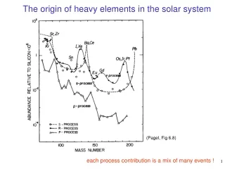
Universality of the Mott transition Crossover: bad insulator to bad metal Critical point First order MIT Ni2-xSex k organics V2O3 1B HB model (DMFT):
How to computed spectroscopic quantities (single particle spectra, optical conductivity phonon dispersion…) from first principles? How to relate various experiments into a unifying picture. New concepts, new techniques….. DMFT maybe simplest approach to meet this challenge Basic questions to address
DMFT + electronic structure method Basic idea of DMFT+electronic structure method (LDA or GW): For less correlated bands (s,p): use LDA or GW For correlated bands (f or d): add all local diagrams by solving QIM (G. Kotliar S. Savrasov K.H., V. Oudovenko O. Parcollet and C. Marianetti, RMP 2006). Dyson equation Ce-f orbital hybridization other “light” orbitals obtained by DFT Ce(4f) obtained by “impurity solution” Includes the collective excitations of the system all bands are affected: have lifetime fractional weight Self-energy is local in localized basis, in eigenbasis it is momentum dependent!
DMFT “Bands” are not a good concept in DMFT! instead of “bands” Frequency dependent complex object lifetime effects quasiparticle “band” does not carry weight 1 Spectral function is a good concept Hybridization: In FL regime: at low energy q.p. hybridization becomes at high energy In DMFT:
high T low T DMFT is not a single impurity calculation Auxiliary impurity problem: temperature dependent: Weiss field High-temperature D given mostly by LDA low T: Impurity hybridization affected by the emerging coherence of the lattice (collective phenomena) DMFT SCC: Feedback effect on D makes the crossover from incoherent to coherent state very slow!
Ir In Ce In Ce In Crystal structure of 115’s Tetragonal crystal structure IrIn2 layer 3.27au 4 in plane In neighbors 3.3 au CeIn3 layer IrIn2 layer 8 out of plane in neighbors
ALM in DMFT Schweitzer& Czycholl,1991 Crossover scale ~50K • High temperature • Ce-4f local moments • Low temperature – • Itinerant heavy bands Coherence crossover in experiment out of plane in-plane
? A(w) w k Issues for the system specific study • How does the crossover from localized moments • to itinerant q.p. happen? • How does the spectral • weight redistribute? • Where in momentum space q.p. appear? • What is the momentum • dispersion of q.p.? • How does the hybridization gap look like in momentum space?
(e Temperature dependence of the localCe-4f spectra • At 300K, only Hubbard bands • At low T, very narrow q.p. peak • (width ~3meV) • SO coupling splits q.p.: +-0.28eV SO • Redistribution of weight up to very high • frequency J. H. Shim, KH, and G. Kotliar Science, November 1 2007; 1149064
Buildup of coherence in single impurity case Very slow crossover! coherent spectral weight TK T T* Buildup of coherence coherence peak scattering rate Slow crossover pointed out by NPF 2004 Crossover around 50K
Consistency with the phenomenological approach of NPF +C Remarkable agreement with Y. Yang & D. Pines cond-mat/0711.0789!
Angle integrated photoemission vs DMFT Experimental resolution ~30meV, theory predicts 3meV broad band Surface sensitive at 122eV ARPES Fujimori, 2006
Angle integrated photoemission vs DMFT • Nice agreement for the • Hubbard band position • SO split qp peak • Hard to see narrow resonance • in ARPES since very little weight • of q.p. is below Ef Lower Hubbard band ARPES Fujimori, 2006
Momentum resolved Ce-4f spectra Af(w,k) Hybridization gap q.p. band Fingerprint of spd’s due to hybridization scattering rate~100meV SO Not much weight T=10K T=300K
DMFT qp bands LDA bands LDA bands DMFT qp bands Quasiparticle bands three bands, Zj=5/2~1/200
Momentum resolved total spectra A(w,k) Most of weight transferred into the UHB LDA f-bands [-0.5eV, 0.8eV] almost disappear, only In-p bands remain Very heavy qp at Ef, hard to see in total spectra Below -0.5eV: almost rigid downshift Unlike in LDA+U, no new band at -2.5eV ARPES, HE I, 15K LDA+DMFT at 10K Fujimori, 2003 Large lifetime of HBs -> similar to LDA(f-core) rather than LDA or LDA+U
w k first mid-IR peak at 250 cm-1 CeCoIn5 Optical conductivity F.P. Mena & D.Van der Marel, 2005 Typical heavy fermion at low T: no visible Drude peak no sharp hybridization gap Narrow Drude peak (narrow q.p. band) Hybridization gap second mid IR peak at 600 cm-1 Interband transitions across hybridization gap -> mid IR peak E.J. Singley & D.N Basov, 2002
Optical conductivity in LDA+DMFT • At 300K very broad Drude peak (e-e scattering, spd lifetime~0.1eV) • At 10K: • very narrow Drude peak • First MI peak at 0.03eV~250cm-1 • Second MI peak at 0.07eV~600cm-1
10K In eV Ce In Multiple hybridization gaps non-f spectra 300K • Larger gap due to hybridization with out of plane In • Smaller gap due to hybridization with in-plane In
Fermi surfaces of CeM In5 within LDA Localized 4f: LaRhIn5, CeRhIn5 Shishido et al. (2002) Itinerant 4f : CeCoIn5, CeIrIn5 Haga et al. (2001)
LDA (with f’s in valence) is reasonable for CeIrIn5 de Haas-van Alphen experiments Experiment LDA Haga et al. (2001)
Fermi surface reconstruction at 2.34GPa Sudden jump of dHva frequencies Fermi surface is very similar on both sides, slight increase of electron FS frequencies Reconstruction happens at the point of maximal Tc Fermi surface changes under pressure in CeRhIn5 localized itinerant Shishido, (2005) We can not yet address FS change with pressure We can study FS change with Temperature - At high T, Ce-4f electrons are excluded from the FS At low T, they are included in the FS
Slight decrease of the electron FS with T M X M G X X M M X Electron fermi surfaces at (z=0) LDA+DMFT (400 K) LDA LDA+DMFT (10 K) a2 a2
Slight decrease of the electron FS with T No a in DMFT! No a in Experiment! A R A Z R R A A R Electron fermi surfaces at (z=p) LDA+DMFT (400 K) LDA LDA+DMFT (10 K) a3 a3 a
Slight decrease of the electron FS with T M X M G X X M M X Electron fermi surfaces at (z=0) LDA+DMFT (400 K) LDA+DMFT (10 K) LDA b1 b1 b2 b2 c
No c in DMFT! No c in Experiment! Slight decrease of the electron FS with T A R A Z R R A A R Electron fermi surfaces at (z=p) LDA+DMFT (400 K) LDA+DMFT (10 K) LDA b2 b2 c
M X M G X X M M X Hole fermi surfaces at z=0 Big change-> from small hole like to large electron like LDA+DMFT (400 K) LDA+DMFT (10 K) LDA e1 g h h g
A R A Z R R A A R Hole fermi surface at z=p LDA+DMFT (400 K) LDA+DMFT (10 K) LDA No Fermi surfaces
Fermi surfaces Increasing temperature from 10K to 300K: • Gradual decrease of electron FS • Most of FS parts show similar trend • Big change might be expected in the G plane – small hole like FS pockets (g,h) merge into electron FS e1 (present in LDA-f-core but not in LDA) • Fermi surface a and c do not appear in DMFT results
Conclusions • Crossover from local moment regime to heavy fermion state is very slow. • Width of heavy quasiparticle bands is predicted to be only ~3meV. We predict a set of three heavy bands with their dispersion. • Mid-IR peak of the optical conductivity is split due to presence of two type’s of hybridization • Ce moment is more coupled to out-of-plane In then in-plane In • Fermi surface changes gradually with temperature and most of electron FS parts are only slightly decreases with increasing temperature. Hole pockets merge into e1 electron FS.
ARPES of CeIrIn5 Fujimori et al. (2006)
Phase diagram of 115’s Why CeIrIn5? • Ir atom is less correlated than • Co or Rh (5d / 3d or 4d) • CeIrIn5 is more itinerant(coherent) • than Co (further away from QCP)
k Continuous time “QMC” impurity solver, expansion in terms of hybridization K.H. Phys. Rev. B 75, 155113 (2007) General impurity problem Diagrammatic expansion in terms of hybridization D +Metropolis sampling over the diagrams • Exact method: samples all diagrams! • Allows correct treatment of multiplets
Ce 4f partial spectral functions LDA+DMFT (10K) LDA+DMFT (400K) Blue lines : LDA bands