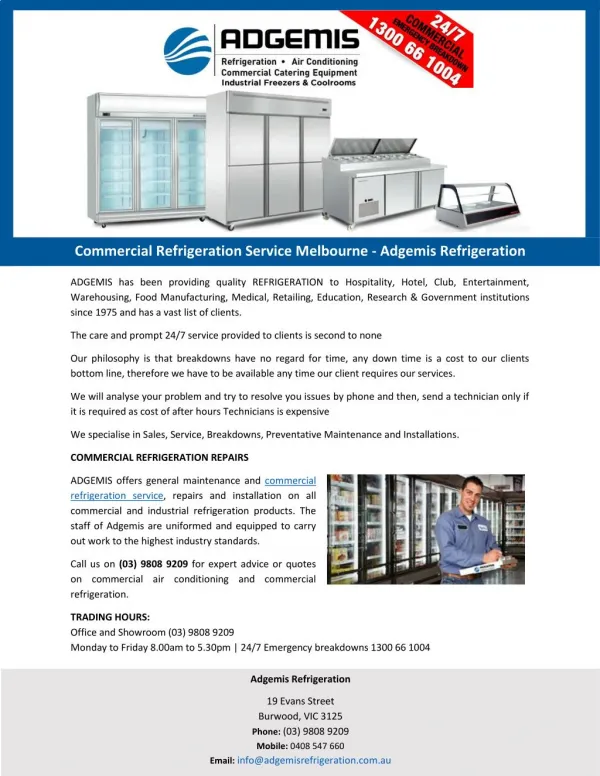
Download
1 / 49
510 likes | 766 Views
SECTION 5 COMMERCIAL REFRIGERATION UNIT 24 EXPANSION DEVICES. UNIT OBJECTIVES. List and describe the three most popular expansion devices Explain the operating characteristics of various expansion valves Explain how various expansion devices respond to load changes

E N D
SECTION 5 COMMERCIAL REFRIGERATION UNIT 24 EXPANSION DEVICES
UNIT OBJECTIVES • List and describe the three most popular expansion devices • Explain the operating characteristics of various expansion valves • Explain how various expansion devices respond to load changes • Describe the operation of balanced port, dual port and electronic • expansion valves • Explain how electronic controllers are used to control expansion • valves After studying this unit, the reader should be able to
EXPANSION (METERING) DEVICES • Meters the correct amount of refrigerant to the evaporator • Installed in the liquid line at the inlet of the evaporator • Common devices: Automatic expansion valve, thermostatic expansion valve, fixed bore (capillary tube) • Less common devices: High-side float, low-side float
Compressor Condenser Direction of Refrigerant Flow Evaporator Metering device
THERMOSTATIC EXPANSION VALVE (TXV) • Maintains a constant evaporator superheat • If the evaporator superheat is high, the valve will open • Superheat ensures that no liquid refrigerant leaves the evaporator • Low superheat increases the net refrigerant effect
Transmission Line Evaporator Thermal Bulb Thermostatic Expansion Valve Liquid Line Direction of Refrigerant Flow
TXV COMPONENTS • Valve body • Diaphragm • Needle and seat • Spring • Adjustment and packing gland • Sensing bulb and transmission tube
THE VALVE BODY • Machined brass or stainless steel • Holds components together • Provides means to connect valve to the piping circuit • Fastened by flare, solder, or flange • Has an inlet screen to stop any small particulate matter from entering valve
THE DIAPHRAGM • Moves the needle in and out of the seat in response to system load changes • Flexes downward to open the valve • Flexes upward to close the valve • Made of thin, flexible stainless steel • Located at the top of the valve
Bulb pressure pushes down to open the valve Diaphragm Evaporator pressure pushes up to close the valve Spring pressure pushes up to close the valve
NEEDLE AND SEAT • Control refrigerant flow through the valve • Needle is pushed into the seat to reduce refrigerant flow to the evaporator • Made of stainless steel • The greater the pressure difference across the needle and seat, the greater the amount of flow through the valve
Diaphragm Seat Push Rods Needle
Diaphragm pushed up Needle pushed into the seat, closing the valve
Diaphragm pushed down Needle pushed out of the seat, opening the valve
THE SPRING • One of the valve’s closing forces • Acts to push the needle into the seat, causing the valve to close • Spring pressure determines the evaporator superheat • Spring tension can be field adjusted • Only EXPERIENCED field technicians should do adjustments on the valve
THE SENSING BULB AND TRANSMISSION LINE • Senses temperature at the outlet of the evaporator • This temperature is converted to a pressure and is transmitted to the top of the diaphragm • The fluid in the bulb responds to a pressure / temperature relationship • When the suction line temperature goes up, the bulb pressure goes up • The bulb pressure is the only opening pressure that controls the valve
Thermal Bulb Transmission Line Valve body Saturated refrigerant to the evaporator Liquid refrigerant from condenser or receiver Superheat spring adjusting screw
TYPES OF BULB CHARGE • Bulb charge is the type and amount of refrigerant contained in the thermal bulb transmission line and the space above the diaphragm • Liquid charge • Vapor charge • Cross liquid charge • Cross vapor charge
THE LIQUID CHARGE BULB • Bulb contains the same refrigerant as the refrigeration system • Under all conditions, the bulb will ALWAYS contain some liquid • The refrigerant in the bulb will always follow the pressure/temperature relationship of the system
THE CROSS LIQUID CHARGE BULB • Bulb contains a different refrigerant than the system • Under all conditions, the bulb will ALWAYS contain some liquid • The bulb does not follow the pressure/ temperature relationship of the system • Valve closes during the compressor off cycle
THE VAPOR CHARGE BULB • Bulb contains the same refrigerant as the system • Bulb only contains a small amount of liquid • Also called a critical charge bulb • At some predetermined temperature, all of the liquid in the bulb will boil until only vapor remains • Any further increases in bulb temperature will have no effect on the bulb pressure
THE CROSS VAPOR CHARGE BULB • Bulb contains a different refrigerant than the system • Bulb only contains a small amount of liquid • Also called a critical charge bulb • At some predetermined temperature, all of the liquid in the bulb will boil until only vapor remains • Any further increases in bulb temperature will have no effect on the bulb pressure
EXAMPLE OF A TXV WITH INTERNAL EQUALIZER – LIQUID-FILLED BULB • Normal load conditions – medium temperature application, R-134a, valve is in equilibrium • Suction pressure 18.4 psig • Suction line temperature 30°F, PBULB= 26.1 psig • PSPRING + PEVAPORATOR = PBULB • Spring pressure + 18.4 psig = 26.1 psig • Spring pressure = 7.7 psig
30°F 26.1 psig Spring pressure = ? Evaporator pressure 18.4 psig 26.1 psig = Ps + 18.4 psig Ps = 7.7 psig R-134a
LOAD CHANGES WITH FOOD ADDED TO COOLER • Addition of warm food increases evaporator load • Refrigerant boils faster and suction pressure rises • Evaporator superheat rises • Valve opens to feed more refrigerant to the evaporator • Increased evaporator superheat causes temperature of remote bulb to rise
LOAD CHANGES WITH FOOD REMOVED FROM THE COOLER • Removal of food reduces load on the evaporator • Refrigerant boils slower and suction pressure drops • Evaporator superheat drops • Valve closes to feed less refrigerant to the evaporator
TXV WITH EXTERNAL EQUALIZER • Used if an evaporator has more than a 2.5 psig drop from inlet to outlet • The evaporator pressure is sensed at the outlet of the coil instead of the inlet • Used to prevent the coil from starving • Connected to the evaporator outlet after the thermal bulb • Used to compensate for pressure drop in the evaporator
External equalizer line connected to the outlet of the evaporator coil Diaphragm Solid brass divider Evaporator pressure pushing up on the diaphragm Saturated refrigerant to the evaporator Liquid refrigerant to the expansion valve
TXV RESPONSES TO LOAD CHANGES • When load increases • Refrigerant boils faster and the suction line temperature increases • Valve opens to feed more refrigerant to the evaporator • When load decreases • Refrigerant takes longer to boil • Valve closes to feed less refrigerant to the evaporator
BALANCED PORT TXV • Designed to operate in low ambient conditions • Used if any of the following conditions exist - Large varying head pressures - Large varying pressure drops across the TXV - Widely varying evaporator loads - Very low liquid line temperatures • Have larger-than-normal orifices
DUAL PORT TXV • Used when systems need a larger TXV for short periods of time • Dual-port valves have two independent capacities - Larger port for periods of high load - Smaller port for periods of normal load - TXV capacity is doubled when larger port is open all the way
PRESSURE LIMITING TXV • Allows evaporator pressure to only reach a predetermined pressure • If the evaporator pressure exceeds this pressure, the valve will close • Desirable on low-temperature applications
SENSING ELEMENT (BULB) INSTALLATION • Bulb should be mounted on the suction line as close to the evaporator as possible • Suction line should be clean and straight • Bulb should be mounted securely • Follow manufacturer’s instructions • For small suction lines, the bulb is usually secured to the top of the line
Thermal bulb mounted on top of the line Use strapping material supplied with the valve to hold bulb securely to the suction line Thermal bulb located 45° below horizontal Suction line smaller than 3/4” Suction line larger than 3/4”
THE SOLID-STATE CONTROLLED EXPANSION VALVE • Uses a thermistor as a sensing element • Electrically controlled • When coil is energized, the valve opens • Responds very quickly to temperature changes • Suitable for heat pump applications
STEP MOTOR EXPANSION VALVES • Uses a small motor to control the valve port • Valve port controls evaporator superheat • Temperature sensor sends a signal to the controller • The controller sends a signal to the motor • The motor turns a fraction of a rotation for each controller signal
ALGORITHMS AND PID CONTROLLERS • Proportional Controllers - Generate an analog output signal - Difference between actual superheat and superheat set point is the “offset” or “error” • Integral Controller Modes - Helps reduce the “error” or “offset” - Calculates error size and the length of time the error exists • Derivative Controller Modes - Estimate rate of change of temperature/time curve
AUTOMATIC EXPANSION VALVE • Maintains constant pressure in the evaporator • When the evaporator pressure drops, the valve opens • The spring pressure pushes to open the valve • The evaporator pressure pushes to close the valve • Turning the adjustment screw into the valve increases the spring pressure
Spring pressure pushes down to open the valve Diaphragm Two pressures control the automatic expansion valve Evaporator pressure pushes up to close the valve
Diaphragm pushed up Needle pushed into the seat, closing the valve Caused by an increase in evaporator pressure
Diaphragm pushed down Needle pushed out of the seat, opening the valve Caused by a decrease in evaporator pressure
Spring pressure Spring Diaphragm Needle and Seat Saturated refrigerant to the evaporator Liquid refrigerant from condenser or receiver Evaporator pressure
AUTOMATIC EXPANSION VALVE RESPONSE TO LOAD CHANGES • Responds in reverse to load changes • If the load increases • Refrigerant boils faster in the evaporator • The evaporator pressure increases • The valve closes • Used where the load is fairly constant
THE CAPILLARY TUBE METERING DEVICE • Controls refrigerant flow by the pressure drop across it • Diameter and length of the tube determine flow at a given pressure • Does not maintain evaporator pressure or superheat • Used when the load is relatively constant • No moving parts to wear out
OPERATING CHARGE FOR THE CAPILLARY TUBE SYSTEM • Capillary tube systems are critically charged • All refrigerant in the system circulates at all times when the system is running • Capillary tube sometimes fastened to the suction line for heat exchange • Responds very slowly to system load changes
UNIT SUMMARY - 1 • Expansion devices meter the correct amount of refrigerant to the evaporator according to system operating conditions • Common expansion valves include the capillary tube, automatic expansion valve and the thermostatic expansion valve • The thermostatic expansion valve is designed to maintain constant superheat in the evaporator
UNIT SUMMARY - 2 • Three pressures control the operation of the TXV: the bulb pressure, the spring pressure and the evaporator pressure • Thermal bulb can be liquid-charged, vapor-charged, cross liquid-charged, or cross vapor-charged • Internally equalized TXVs get the evaporator pressure from the inlet of the coil, while externally equalized TXVs get the evaporator pressure from the outlet of the coil
UNIT SUMMARY - 3 • Special TXVs include the balanced port TXV, the dual port TXV and the electronic TXV • The automatic expansion valve maintains a constant evaporator pressure • Two pressure control the AXV: the spring pressure and the evaporator pressure • The capillary tube is a fixed bore metering device • The capillary tube meters refrigerant depending on the pressure drop across the tube