Download
1 / 33
380 likes | 833 Views
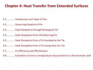
Extended Surfaces. Chapter Three Section 3.6. Lecture 6. Nature and Rationale of Extended Surfaces. Nature and Rationale. An extended surface (also know as a combined conduction-convection system or a fin ) is a solid within which heat transfer by conduction is assumed to be

E N D
Extended Surfaces Chapter Three Section 3.6 Lecture 6
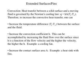
Nature and Rationale of Extended Surfaces Nature and Rationale • An extended surface (also know as a combined conduction-convection system • or a fin) is a solid within which heat transfer by conduction is assumedto be • one dimensional, while heat is also transferred by convection (and/or • radiation) from the surface in a direction transverse to that of conduction. • If heat is transferred from the surface to the fluid by convection, what • surface condition is dictated by the conservation of energy requirement? • Why is heat transfer by conduction in the x-direction not, in fact, one- dimensional?
How does vary with x? They are particularly beneficial when is small, as for a gas and natural convection. Nature and Rationale (cont.) • What is the actual functional dependence of the temperature distribution in • the solid? • If the temperature distribution is assumed to be one-dimensional, that is, • T=T(x) , how should the value of T be interpreted for any x location? • When may the assumption of one-dimensional conduction be viewed as an excellent approximation? The thin-fin approximation. • Extended surfaces may exist in many situations but are commonly used as • fins to enhance heat transfer by increasing the surface area available for • convection (and/or radiation). • Some typical fin configurations: Straight fins of (a) uniform and (b) non-uniform cross sections; (c) annular fin, and (d) pin fin of non-uniform cross section.
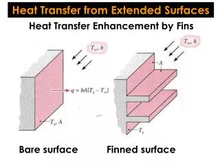
Heat Transfer from Extended Surfaces Extended Surface to Increase Heat Transfer Rate
Heat Transfer from Extended Surfaces Extended Surface to Increase Heat Transfer Rate Three ways to increase q Increase h Reduce Increase A
Heat Transfer from Extended Surfaces Applications of Fins
Heat Transfer from Extended Surfaces A General Conduction Analysis
Heat Transfer from Extended Surfaces Applying Conservation of energy to the differential element: From Fourier’s Law
Heat Transfer from Extended Surfaces From Taylor Series Expansion: Heat of Convection
Heat Transfer from Extended Surfaces Heat Transfer Eqn: Or
Fins of Uniform Section Area Heat Transfer Eqn: Where dAs/dx = P (fin perimeter), dAC/dx = 0 Define Excess Temperature
Fins of Uniform Section Area Define: Heat Transfer Eqn.: General Solution
Fins of Uniform Section Area Need Two b.c.’s to evaluate C1 and C2.
Fins of Uniform Section Area b.c.-1: b.c.-2: Or b.c.-2 From b.c.-1: From b.c.-2:
Fins of Uniform Section Area Solving for C1 and C2: The hyperbolic function definitions (Page 1014):
Fins of Uniform Section Area Overall Heat Transfer Rate: Above equation can be obtained from energy conservation of the fin.
Fins of Uniform Section Area If the fin tip is adiabatic (second tip b.c.)
Fins of Uniform Section Area If the fin tip is at constant T (Third tip b.c.)
Fins of Uniform Section Area If the fin is very long (Fourth tip b.c.)
Example 3.9 (pages 162-164) A very long rod 5 mm in diameter has one end maintained at 100 ºC. The surface of the rod exposed to ambient air at 25 ºC with a convection heat transfer coefficient of 100 W/m2 K. 1. Determine the temperature distributions along rods constructed from pure copper, 2024 aluminum alloy, and type AISI 316 stainless steel. What are the corresponding heat losses from the rods? 2. Estimate how long the rods must be for the assumption of infinite length to yield accurate estimate of the heat loss.
Example 3.9 Known:A long circular rod exposed to ambient air Find: 1. T distribution and heat loss when rod is fabricated from copper an aluminm alloy, or stainless steel 2. How long rods must be to assume infinite length Schematic:
Example 3.9 Assumptions: • Steady-state; • 1-D conduction in x direction; • Constant properties. • Negligible radiation; • Uniform heat transfer coefficient; • Infinite long rod Properties:
Example 3.9 1/2
Example 3.9 Comments: The mL 2.65 was based on heat loss. If the requirement is to predict the T distribution accurately, a larger mL value (4.6) is needed. It was based on exp(-mL)<0.01.
Problem 3.126 3.126Turbine blades mounted to a rotating disc in a gas turbine engine are exposed to a gas stream that is at T=1200 ºC and maintains a convection coefficient of h=250 W/m2 K over the blade. The blades, which are fabricated from Inconel, k 20 W/m K, have a length of L=50 mm. The blade profile has a uniform cross-sectional area of A=6xl0-4m2 and a perimeter of P =110 mm. A proposed blade-cooling scheme, which involves routing air through the supporting disc, is able to maintain the base of each blade at a temperature of T = 300 ºC.
Problem 3.126 (a). If the maximum allowable blade temperature is 1050 ºC and the blade tip may be assumed to be adiabatic, is the proposed cooling scheme satisfactory? (b) For the proposed cooling scheme, what is the rate at which heat is transferred from each blade to the coolant?
Problem: Turbine Blade Cooling Problem 3.126: Assessment of cooling scheme for gas turbine blade. Determination of whether blade temperatures are less than the maximum allowable value (1050°C) for prescribed operating conditions and evaluation of blade cooling rate. Schematic: Assumptions: (1) One-dimensional, steady-state conduction in blade, (2) Constant k, (3) Adiabatic blade tip, (4) Negligible radiation. Analysis: Conditions in the blade are determined by Case B of Table 3.4. (a) With the maximum temperature existing at x = L, Eq. 3.80 yields
From Table B.1 (or by calculation), Hence, Problem: Turbine Blade Cooling (cont.) and, subject to the assumption of an adiabatic tip, the operating conditions are acceptable. Eq. 3.81 and Table B.1 yield Hence, < Comments: Radiation losses from the blade surface contribute to reducing the blade temperatures, but what is the effect of assuming an adiabatic tip condition? Calculate the tip temperature allowing for convection from the gas.