Grid Connect
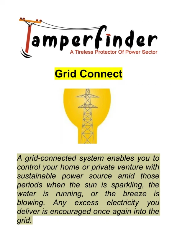
Grid Connect. Session 13 System Protection. Grid Connect Session12. System Protection. System Protection is designed to protect cabling & PV modules PV modules generate current in relation to the solar irradiance available in the installation plane.

Grid Connect
E N D
Presentation Transcript
Grid Connect Session 13 System Protection J.P. Teasel version 12/11/2011.1
Grid Connect Session12 System Protection • System Protection is designed to protect cabling & • PV modules • PV modules generate current in relation to the solar irradiance available in the installation plane. • PV modules are a ‘current limited ‘power source (irradiance available to them is finite) • However damaging fault currents may be generated in the PV array i.e. shading causing a single module/ string not to generate current or an earth fault • If enough cells are hard shaded, the module will not convert any energy and will, in fact, become a tiny drain of energy on the entire system. J.P. Teasel version 12/11/2011.1
Grid Connect Session12 System Protection What part of the Grid connected PV System is considered to be prescribed electrical installation work? (also see next slide) Those parts of the generation system operating at or above 120 Volt dc, cables installed between panels and between the array and inverter and the ac cables installed between the inverter and the switchboard to which the generation system is connected along with all the required isolation and protection devices, are prescribed electrical installation work. J.P. Teasel version 12/11/2011.1
Grid Connect Session12 System Protection What part of the Grid connected PV System is considered to be prescribed electrical installation work? (continued) . For the purpose of section 45 of the Electricity Safety Act 1998, prescribed electrical Installation work means work on all or any part of the following electrical installations if they ordinarily operate at low voltage or a voltage exceeding low voltage. (f) Wiring systems, switchgear, control gear and accessories installed to provide control and protection of generation systems (excluding stand alone power systems with a power rating that is less than 500 volt-amperes) J.P. Teasel version 12/11/2011.1
Grid Connect Session12 System Protection The following activities are considered to be prescribed electrical installation work; Adding panels to an existing solar grid connected PV where the open circuit voltage (Voc Array) exceeds Extra Low Voltage. Upgrading the inverter due to increase in generation capacity The replacement of one component part of prescribed electrical installation work ‘like for like‗ such as an inverter or isolator can be entered on a non-prescribed certificate without the mandatory inspection. Reference – Electricity Safety (Installations) Regulations 2009 – Regulation 238(3) J.P. Teasel version 12/11/2011.1
Grid Connect Session12 System Protection Voltage Differences in potential normally existing between conductors and conductors and earth as follows: Extra Low Voltage: not exceeding 50 V ac or 120 V ripple-free dc Low voltage: Exceeding extra-low voltage, but not exceeding 1000 V ac or 1500 V dc High Voltage: Exceeding Low-voltage. Reference - AS/NZS 3000:2007 Amd1 Clause 1.4.98 Voltage J.P. Teasel version 12/11/2011.1
Grid Connect Session12 System Protection What is Class II equipment (double insulated) also see next slides1/4 Equipment in which protection against electric shock does not rely on basic insulation only, but in which additional safety precautions such as double insulation or reinforced insulation are provided, there being no provision for protective earthing or reliance upon installation conditions. Equipment may be one of the following types: abc . J.P. Teasel version 12/11/2011.1
Grid Connect Session12 System Protection What is Class II equipment (double insulated) slide2/4 : (a) Equipment having durable and substantially continuous enclosures of insulating material which envelops all metal parts, with the exception of small parts, such as nameplates, screws and rivets, which are isolated from live parts by insulation at least equivalent to reinforced insulation; such equipment is called insulation-encased Class II equipment. (b next slide)…………. J.P. Teasel version 12/11/2011.1
Grid Connect Session12 System Protection What is Class II equipment (double insulated) continued…………. Slide3/4 (b) Equipment having a substantially continuous metal enclosure, in which double insulation is used throughout, except for those parts where reinforced insulation is used, because the application of double insulation is manifestly impracticable; such equipment is called metal-encased Class II equipment. (c) Equipment that is a combination of the types described in Items (a) and (b). see next slide NOTES: J.P. Teasel version 12/11/2011.1
Grid Connect Session12 System Protection What is Class II equipment (double insulated) continued…………. Slide4/4 NOTES: 1. The enclosure of insulation-encased Class II equipment may form part of the whole of the supplementary insulation or of the reinforced insulation. 2. If the equipment with double insulation or reinforced insulation throughout has an earthing terminal or earthing contact, it is considered to be of Class I construction. 3. Class II equipment may be provided with means for maintaining the continuity of protective circuits, insulated from accessible conductive parts by double insulation or reinforced insulation. 4. Class II equipment may have parts operating at SELV Reference – AS/NZS 5033 Clause 1.4.8 Class II equipment J.P. Teasel version 12/11/2011.1
Grid Connect Session12 System Protection What is a separated circuit? Separated low voltage A low voltage system that is electrically separated from earth and from other systems in such a way that a single fault cannot give rise to the risk of electric shock ELECTRICAL SEPARATION (ISOLATED SUPPLY) The expression ‘electrical separation‘ has the same meaning as isolated supply‘. ‘Electrical separation‘ is used throughout this document. J.P. Teasel version 12/11/2011.1
Grid Connect Session12 System Protection Electric Shock 1/2 Several methods of protection against electric shock arising from indirect contact are recognised by Clause 1.5.5 of AS/NZS 3000:2007. These methods include that of protection by electrical separation of the supply. Protection by electrical separation is an alternative to other recognised methods and is intended, in an individual circuit, to prevent shock current through contact with exposed conductive parts that might be energized by a fault in the basic insulation of that circuit. See next slide J.P. Teasel version 12/11/2011.1
Grid Connect Session12 System Protection Electric Shock cont… 2/2 Protection by electrical separation shall be afforded by compliance with Clauses 7.4.2 to 7.4.4, of AS/NZS 3000:2007 and with — Clause 7.4.5 of AS/NZS 3000:2007 for a supply to one item of equipment; or (b) Clause 7.4.6 of AS/NZS 3000:2007 for a supply to more than one item of equipment. NOTE: Figure 7.7 of AS/NZS 3000:2007 provides an illustration of a separated supply to single and multiple items of equipment. Reference – AS/NZS 3000:2007 Clause 7.4 J.P. Teasel version 12/11/2011.1
Grid Connect Session12 System Protection AS/NZS5033: 2.4.3 PV strings Where there are more than Np parallel connected strings, fault current protection shall be installed unless the array is ELV and— (i.e. there are more than 3 strings) the PV modules are mounted in such a way and location that an arc or molten metal coming out of the back of any of the PV modules shall not result in property damage or risk to the lives of people or animals; or (b) the PV modules are of a type which prevents any molten metal coming out of the back of the module. J.P. Teasel version 12/11/2011.1
Grid Connect Session12 System Protection AS/NZS5033: 2.4.3 PV strings The rated trip current (I trip) of fault current protection devices for PV strings shall be as specified by the PV module manufacturer. If the manufacturer does not give any recommendation, Itrip shall be determined by the following formula: 1.25 × I sc mod ≤ I trip ≤ 2 ×I sc mod (in english the circuit breaker or fuse will be of a rating between these values) J.P. Teasel version 12/11/2011.1
System Protection Grid Connect Session13 5.5A String fuse protection: When is it required & when not? Example Module Sunshine Model S185 Isc 5.5A Maximum series fuse rating 15A Max fault current 5.5A No fault protection required Faulty Shaded module Output current 5.5A 11A Max fault current 11A No fault protection required Faulty Shaded module Output current 5.5A Output current 5.5A 16.5A Max fault current 16.5A fault protection required Faulty Shaded module Output current 5.5A Output current 5.5A Output current 5.5A Output current 5.5A J.P. Teasel version 12/11/2011.1
Grid Connect Session12 System Protection • AS/NZS 5033:2005 Clause 3.4.1(table 3.1) • String Cable sizing • No downstream fault current protection device therefore cable must carry min. current 1.25 x Isc mod x(no. of parallel strings -1) • 1.25 x 5.5 x (3-1) = 13.75A min • (13.75A<Max.series fuse rating = 20A) Isc=5.5A Voc = 44.5V Imp= 4.95A Vmp = 35.4V Pmp = 175W Max.series fuse rating = 20A ‡‡ ‡ ‡‡‡ AS/NZS 5033:2005 Clause 2.4.1 No of string fault current protection required Disconnection means still required Clause 2.5.3 Np = max. series fuse rating/Isc=20/5.5= 3.6 round up Np =4 J.P. Teasel version 12/11/2011.1
Grid Connect Session12 System Protection • AS/NZS 5033:2005 Clause 3.4.1(table 3.1) • String Cable sizing must carry current of protective device i.e. 10A • 1.25 x 5.1 x (5-1) = 25.5A min which exceeds max. series fuse rating of 20A • fault current protection device required • 10A was chosen carry min. current 1.25 x Isc mod Isc=5.1A Voc = 44.2V Imp= 4.7A Vmp = 35.2V Pmp = 165W Max.series fuse rating = 20A ‡‡ ‡‡‡ Np = max. series fuse rating/Isc=20/5.1= 3.9 round up Np =4 String cable sizing/ fault protection device ‡‡ ‡‡‡ AS/NZS 5033:2005 Clause 2.4.3 & 2.5.3 Number of strings greater than Np (we calculated 4) String fault current protection &disconnection required each string Single pole floating double insulated Rated trip current protection device must be between 1.25 x Isc mod & 2 x Isc mod 1.25 x5.1 =6.375 &2x 5.1 = 10.2 10A ok J.P. Teasel version 12/11/2011.1
Grid Connect Session12 System Protection • AS/NZS 5033:2005 Clause 3.4.1(table 3.1) • PV Array Cable sizing • 1.25 x Isc string • 1.25x [( 5.1 x (5-1)) = 25.5A] =31.9A Isc=5.1A Voc = 44.2V Imp= 4.7A Vmp = 35.2V Pmp = 165W Max.series fuse rating = 20A ‡‡ ‡‡‡ ARRAY cable sizing/ fault protection device ‡‡ ‡‡‡ AS/NZS 5033:2005 Clause 2.4.5 No fault current protection required on the PV array cable-there are no batteries Disconnection still required Clause 2.5.3 J.P. Teasel version 12/11/2011.1
Grid Connect Session12 System Protection • AS/NZS 5033:2005 Table (2.3) • String Disconnection means • A readily available disconnection device both positive & negative legs) Isc=5.1A Voc = 44.2V Imp= 4.7A Vmp = 35.2V Pmp = 165W Max.series fuse rating = 20A ‡‡ ‡‡‡ String & array fault protection /disconnection ‡‡ ‡‡‡ AS/NZS 5033:2005 Table 2.3 Double pole, readily available, load breaking disconnection device lockable in the off position J.P. Teasel version 12/11/2011.1
Grid Connect Session12 System Protection • AS/NZS 5033:2005 Table (2.3) • String Disconnection means • A readily available disconnection device both positive & negative legs) • Can be achieved by plug/socket/ or by virtue of using the DC circuit breaker Isc=5.1A Voc = 44.2V Imp= 4.7A Vmp = 35.2V Pmp = 165W Max.series fuse rating = 20A ‡‡ ‡‡‡ String & array fault protection /disconnection ‡‡ ‡‡‡ AS/NZS 5033:2005 Open circuit voltage is low voltage (LV) requires separation into ELV segments J.P. Teasel version 12/11/2011.1
Grid Connect Session12 System Protection J.P. Teasel version 12/11/2011.1
Grid Connect Session12 System Protection MAIN SWITCHBOARD PV Array Load isolator d.c. isolator Inverter AC isolator Solar supply isolating switch • MSB NET METERING • main • switch Service fuse x x x x LOCAL SERVICE RULES LOCAL SERVICE RULES Ccts no RCD /with RCD protection Schematic diagram of a Grid Connected PV system ) NB: System Protection derived from AS/ NZS 50332005 J.P. Teasel version 12/11/2011.1
Grid Connect Session12 System Protection • Standards and regulations for installation • The following standards and regulations shall be complied with where applicable. • Electrical Safety Act 1998 • Electricity Safety (Installations) Regulations 2009 • NSW Service and Installation Rules 2011 • AS/NZS 3000:2007 Wiring Rules • AS/NZS 3008.1.1:2009 Electrical Installations-Selection of cables • AS/NZS 4777.1:2005 Grid connection of energy systems via Inverters –Installation requirements • AS/NZS 4777.2:2005 Grid connection of energy systems via Inverters –Inverter requirements • AS/NZS 4777.3:2005 Grid connection of energy systems via Inverters –Grid protection requirements • AS/NZS 5033:2005 Installation of photovoltaic (PV) arrays J.P. Teasel version 12/11/2011.1
Grid Connect Session12 System Protection • There are two types of protection devices required in PV systems for safety • Over-current protection • Disconnection means (which can be either :Load-breaking or non load breaking) • Polarised or non polarised • Over-current protection and disconnection devices requirement need assessing at the following system levels • String • Sub-array • array J.P. Teasel version 12/11/2011.1
Grid Connect Session12 System Protection PV ARRAY DIAGRAM: CASE WHERE ARRAY NOT DIVIDED INTO SUB-ARRAYS J.P. Teasel version 12/11/2011.1
Grid Connect Session12 System Protection PV ARRAY DIAGRAM: CASE WHERE ARRAY IS DIVIDED INTO SUB-ARRAYS J.P. Teasel version 12/11/2011.1
Grid Connect Session12 System Protection • Fault current protection • The need for current protection in PV array occurs when other strings in the array feed current into a single string of the array is affected by shading or an earth fault • Current feed back from other strings in the array may be grater than the current which can safely handled by modules in that string • some manufactures specify ‘maximum series fuse rating’ also known as ‘reverse current rating’ this is not an actual fuse within the module • It is the maximum current that can pass through the module with damaging it J.P. Teasel version 12/11/2011.1
Grid Connect Session12 System Protection How to determine when Fault Current Protection is required It is required, whenever the combined short circuit current of all the strings in the array , minus one, is greater that the reverse current rating of the models in the remaining string Isc x (No of strings -1) ≥ Module Reverse Current Rating J.P. Teasel version 12/11/2011.1
Grid Connect Session12 System Protection • How to determine Np • where Np is the maximum number of parallel strings without protection • No = I mod reverse if not a whole round up Isc mod Worked example :If a PV module has a reverse current rating of 15a and a short circuit current of 5.5 A then Np =15/5.5 = 2.27 therefore round up to 3 AS/NZS 5033 2.4.1 Number of parallel strings without overcurrent protection The maximum number of strings connected in parallel without overcurrent protection shall be nP where nP is related to the PV modules reverse current rating and is given by Table 2.1 unless the conditions of Clause 2.4.3 apply. If IMOD REVERSE is not obtainable from the manufacturer of the PV modules, nP shall be taken as 1 J.P. Teasel version 12/11/2011.1
System Protection Grid Connect Session13 5.5A String fuse protection: When is it required & when not? Example Module Sunshine Model S185 Isc 5.5A Maximum series fuse rating 15A Max fault current 5.5A No fault protection required Faulty Shaded module Output current 5.5A 11A Max fault current 11A No fault protection required Faulty Shaded module Output current 5.5A Output current 5.5A 16.5A Max fault current 16.5A fault protection required Faulty Shaded module Output current 5.5A Output current 5.5A Output current 5.5A Output current 5.5A J.P. Teasel version 12/11/2011.1
Grid Connect Session12 System Protection LOCATION OF FAULT CURRENT PROTECTION DEVICES Fault current protection devices, where required by Clauses 2.4.2 through 2.4.5 for PV strings, PV sub-arrays and PV arrays, shall be at the load (downsteam) end of those cables. NOTE: Because PV strings/arrays are inherently current limited, the source of fault current is likely to be from other parallel connected strings/sub-arrays. Hence, the protection needs to be near the parallel connection point (i.e. the load end) Source: http://www.solarbos.com/products.php J.P. Teasel version 12/11/2011.1
Grid Connect Session12 System Protection J.P. Teasel version 12/11/2011.1
Grid Connect Session12 System Protection J.P. Teasel version 12/11/2011.1
Grid Connect Session12 System Protection J.P. Teasel version 12/11/2011.1
Grid Connect Session12 System Protection J.P. Teasel version 12/11/2011.1
Grid Connect Session12 System Protection Do I need to install an isolating device at the PV array location that can isolate the dc cable to the inverter? Also see next slide exceptionsYes - each electricity generation system shall be provided with an isolating switch, in accordance with Clause 2.3.2.2 of AS/NZS 3000:2007, that — shall be installed adjacent to, or on, the electricity generation system so that a person operating the switch has a clear view of any person working on the electricity generation system; see next slide J.P. Teasel version 12/11/2011.1
Grid Connect Session12 System Protection Do I need to install an isolating device at the PV array location that can isolate the dc cable to the inverter? Cont………and shall be d.c. rated, double pole, non polarised; and may be combined with overcurrent protection required by Clause 7.3.5.1 of AS/NZS 3000:2007; and shall be under manual control only; and shall not be capable of being overridden or bypassed by programmable control systems or the like. Also see next slide exceptions J.P. Teasel version 12/11/2011.1
Grid Connect Session12 System Protection Do I need to install an isolating device at the PV array location that can isolate the dc cable to the inverter? Continued Exception: The internal isolation arrangements for systems, in accordance with AS 4509.1 or AS 4777, are deemed to satisfy these requirements. Reference - Clause 7.3.4 of AS/NZS 3000:2007 Each dc solar supply cable shall be capable of being isolated at the PV array and be appropriately rated (rated for current, voltage and IP). The installation of the isolation device is mandatory for emergency services to disconnect the supply under emergency conditions. Reference- Victorian Electrical Inspectors Guidance notes March-2010 J.P. Teasel version 12/11/2011.1
Grid Connect Session12 System Protection 2.5.3 Disconnection device requirements Table 2.3 specifies disconnection device requirements for PV array installations. Table 2.4 specifies the location of these devices, when required. J.P. Teasel version 12/11/2011.1
Grid Connect Session12 System Protection Do I need to provide isolation for the PV array (dc) cable at or near the inverter? Yes - it requires an appropriately rated dc device unless the inverter is physically integral with the energy source. Isolation of the inverter from the energy source – an isolation device shall be provided between the energy source and the inverter unless the inverter is physically integral with the energy source. This device shall comply with the requirements for devices for isolation and switching in AS/NZS3000 and be capable of safely breaking voltage and current under both normal and fault conditions. Reference AS/NZS 4777.1 -2005 Clause 5.4 J.P. Teasel version 12/11/2011.1
Grid Connect Session12 System Protection DC isolation & switching devices – general requirements (also see next slide) All switching devices shall comply with all the following requirements: Be rated for dc use. (b) Have a voltage rating equal to, or greater than, 1.2 X VOC ARRAY. (c) Not have exposed metallic live parts in the connected or disconnected state. In addition non-load-breaking switches shall have a current rating equal to, or greater than, their associated fault current protection device, or in the absence of such device, have a current rating equal to, or greater than, the required current carrying capacity of the circuit to which they are fitted. Cont…next silde J.P. Teasel version 12/11/2011.1
Grid Connect Session12 System Protection DC isolation & switching devices – general requirements (continued) AS/NZS5033 Clause 4.3.3 Current breaking devices In addition circuit breakers and any other load breaking disconnection devices used for protection and/or disconnecting means shall comply with all the following requirements: a) Not be polarity sensitive (as fault currents in a PV array may flow in the opposite direction to normal operating currents) except for the PV array main switch in systems without batteries. (see next slide b &c ) J.P. Teasel version 12/11/2011.1
Grid Connect Session12 System Protection DC isolation & switching devices – general requirements (continued) (b) Be rated to interrupt full load and prospective fault currents from the PV array and any other connected power sources (e.g. batteries, generators and the grid). (c) When fault current protection is incorporated, the trip current shall be rated according to fault current protection requirements. also see next slide J.P. Teasel version 12/11/2011.1
Grid Connect Session12 System Protection The PV Array double-pole isolator specified on the dc side of the inverter is required to be a load breaking isolator, but many installers are using double pole dc circuit-breakers because they are readily available. These dc circuit-breakers can be polarized or non-polarized. It is anticipated that the new version of AS/NZS 5033 will not allow polarized breakers to be used. Additional Information is available from ‘Correct wiring of double pole dc Circuit-breakers‘ - published by Global Sustainable Energy Solutions. J.P. Teasel version 12/11/2011.1
Grid Connect Session12 System Protection It is essential that polarized breakers are wired correctly as they are a potential fire hazard when incorrectly wired. Reference- Global Sustainable Energy Solutions –Inspecting the PV Array dc Isolators (Circuit Breakers) J.P. Teasel version 12/11/2011.1
Grid Connect Session12 System Protection • Do I need to link the dc circuit breakers when there are multiple dc supplies feeding into an inverter? • It is desirable to link the circuit breakers for the isolation of supply, but it‘s not mandatory. • If the circuit breakers are not linked there is a possibility that there is a voltage on the load side of the circuit breaker that is turned off. • A sign advising users to isolate all dc supplies is required. J.P. Teasel version 12/11/2011.1
Grid Connect Session12 System Protection Are all inverters suitably IP rated for outdoor installation? No, not all inverters are suitable to be installed where they exposed to weather. Caution - Inverters with an IP rating can be similar in appearance to those without an IP rating. Check the specifications supplied with the inverter J.P. Teasel version 12/11/2011.1
Grid Connect Session12 System Protection Is there a minimum or maximum height for the installation of an inverter? Yes, the maximum height to the top of the inverter is 2 metres above ground, floor or platform, the minimum height to the bottom of the inverter shall not be less than 500mm from ground, floor or platform. Appears to be a Victorian install rule J.P. Teasel version 12/11/2011.1
Grid Connect Session12 System Protection Do I need to provide isolation for the ac circuit at or near the inverter? Yes, a device that provides isolation is required to be mounted immediately adjacent to the inverter. Exception: the above device is not required to be installed if the inverter is mounted within direct view and within 3 metres of the switchboard. Where the inverter is not in close proximity to the switchboard it supplies, some form of overcurrent protection shall be provided to prevent excessive current flow through the cables feeding into the switchboard unless the inverter is supplied from a current limited source. NOTES: 1. Typically cable lengths of 3 m would be considered as close proximity (close proximity means within 3 metres and within direct view of the switchboard). 2. A solar (PV) array is a current limited source. 3. The preferred location for this overcurrent protection device is at the inverter end of the cable. Reference AS/NZS 4777.1:2005 Clause 5.3.5 &5.4 J.P. Teasel version 12/11/2011.1