Download
1 / 72
720 likes | 751 Views
Explore packet switching, virtual circuits vs datagrams, and routing in unicast networks. Learn about OSI model's network layer, benefits of virtual circuits, and various routing algorithms.

E N D
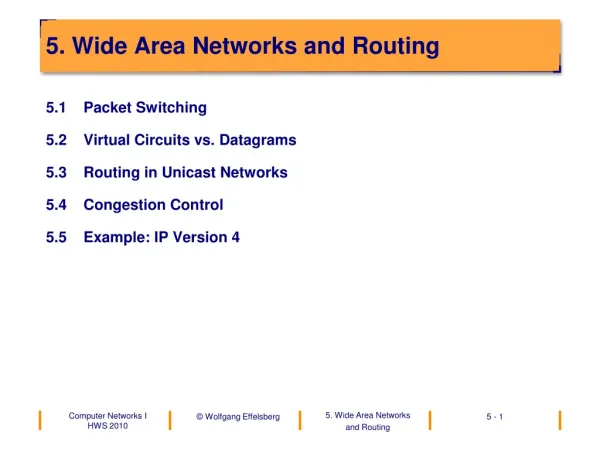
5. Wide Area Networks and Routing • 5.1 Packet Switching • 5.2 Virtual Circuits vs. Datagrams • 5.3 Routing in Unicast Networks • 5.4 Congestion Control • 5.5 Example: IP Version 4
router Application Presentation Session Transport Network Data Link Physical physical medium A physical medium B 5.1 Packet Switching • The Network Layer in the OSI reference model
ISO Definition for the Network Layer • The network layer provides the ability to establish, operate and terminate network connections between open systems over intermediate systems. • The network layer provides independence from routing and switching deci-sions.
Functions of the Network Layer • Routing and switching of packets • Multiplexing of end-to-end connections over a layer-2 connection • Packet segmentation („fragmentation") • In connection-oriented communication the network layer additionally provides • connection establishment and termination • error detection and error correction (end-to-end) • guaranteeing the order of the packets • flow control (end-to-end). • Heterogeneous subnetworks can be interconnected by network layer in-stances ("Internetworking").
5.2 Virtual Circuits vs. Datagrams • Virtual Circuit • The path through the network is determined when the connection is estab-lished, i.e., for each new virtual connection a routing decision takes place in each node only once. The entire traffic flowing over this virtual connection takes the same path through the network. • Datagram • Every packet contains the full address of the destination host. When a packet arrives at an intermediate node the destination address is used to determine the outgoing link for the next hop.
Virtual Circuits • "Perfect" channel through the network • Error control (bit errors, lost and duplicated packets) • Flow control • Order of the messages maintained • Phases • Connection establishment • Data transmission • Connection termination • Advantages • Low overhead for addresses in the data transmission phase • Low computational overhead for routing in the data phase • High quality of the arriving packet stream
Starting from A Starting from B 0 – ABCD 0 – BCD 1 – AEFD 1 – BAE 2 – ABFD 2 – BF 3 – AEC 4 – AECDFB Implementation of Virtual Circuits • Tables with status information on all existing virtual circuits are maintained in each node. • (a) Example of a subnetwork: (b) Eight virtual connections through this subnetwork:
C B B 0 D 0 A 0 C 0 B 1 D 1 H 0 C 1 E 0 H 0 H 1 A 0 E 1 D 2 A 1 F 0 A H 2 F 1 Input Output D F 0 H 0 H 0 B 0 C 0 H 0 H 1 E 0 C 1 H 1 B 0 E 1 F 0 H 2 H 2 B 1 F 1 H 3 E F H 3 E 2 C 2 F 0 A 0 F 0 E 0 D 0 H 4 E 3 A 1 H 0 B 0 D 1 A 2 C 0 B 1 H 0 A 3 C 1 D 0 B 0 Incoming Incoming IMP or Host virtual connection Status Information in the Nodes • (c) Routing tables in the nodes
Datagrams • Every packet (datagram) is considered an isolated unit (like a telegram): • Full destination address contained in every packet • Packets can arrive out of order. • No error control, no flow control in layer 3. • Advantages • Simpler than virtual circuits, therefore easier to implement • No connection establishment and termination phases: low overhead for short-lived connections • More reliable since there are no status clean-up and recovery problems when a node or link fails • Better suitable for internetworking of heterogeneous subnetworks.
5.3 Routing in Unicast Networks • Dependence on Topology • We assume that the network topology is a graph. Note that in LANs with a broadcast topology (bus, ring) routing is not required!
Routing Algorithms (1) • Task • To route the packets through the network from the source end system to the destination end system. • The routing algorithm decides to which outgoing link of each router an in-coming packet is transferred. • Desirable characteristics of a routing algorithm • Correct • Simple • Robust in case of node or link loss • Fair • Optimal (finds the best route, causes minimal overhead)
Routing Algorithms (2) • These design criteria are in conflict. In practice a good approximation is: minimization of hops from the source to the destination.
Classification of Routing Algorithms • 1. Static (non-adaptive) Routing • No consideration of the current network conditions • For all i, j the routes between i and j are determined before the start-up of the network. • No change during operation • 2. Adaptive Routing • Decisions are based on the current network topology (and sometimes load) • Continuous measurement of the topology and the traffic • Can be further classified into • centralized routing algorithms • isolated routing algorithms • distributed routing algorithms
Static Routing • In static routing the entire topology of the network is known to a central node. It computes the optimal paths for each pair (i,j) of nodes, generates routing tables for the individual nodes and sends them out. • Static routing is only possible if the network is relatively small and changes to the topology are rare. • Multipath Routing • Alternative routes are computed for each pair of nodes (i,j). The probability of use depends on the relative weights. Multipath routing is more reliable in case of node or link failures and balances the load better. However it is more complex than single-path routing.
D O1 W1 O2 W2 On Wn æ ö n å = ç ÷ W 1 i è ø = i 1 Multipath Routing (1) • Every node contains a routing table with one row for every destination: D destination Oi ith best outgoing link Wi weight for Oi Wi is the probability that Oi is used.
Multipath Routing (2) • Selection of an alternative: • generate a random number z (0 <= z <= 1) • choose O1 if 0 <= z < W1 • choose O2 if W1 <= z < W1 + W2 • ... • choose On if (W1 + W2 + .. + Wn-1 ) <= z <= 1
A B C D E F G H J K L I Static Routing: Example Topology • Topology of the example network We consider the paths beginning at node J.
Des. 1st choice 2nd choice 3rd choice A A 0.63 I 0.21 H 0.16 B A 0.46 H 0.31 I 0.23 C A 0.34 I 0.33 H 0.33 D H 0.50 A 0.25 I 0.25 E A 0.40 I 0.40 H 0.20 F A 0.34 H 0.33 I 0.33 G H 0.46 A 0.31 K 0.23 H H 0.63 K 0.21 A 0. 16 I I 0.65 A 0.22 H 0.13 - K K 0.67 H 0.22 A 0.11 L K 0.42 H 0.42 A 0.16 Static Routing: Example Table • Static routing table with alternative paths for node j
Determination of Routing Tables • For static routing the routing tables are pre-computed by the network oper-ator. Before network start-up they are loaded into the nodes and not changed anymore. • Characteristics • simple • good results for a constant topology and constant network traffic • But: • inappropriate for strongly varying traffic and changes in topology • inappropriate for large networks (does not scale well) • Still occasionally used In practice. • The network operator always knows the entire topology. He/she can use Dijkstra‘s “shortest path" algorithm once for each node for the construction of the routing tables.
Centralized Adaptive Routing (1) • Principle • There is a Routing Control Center (RCC) in the network. • Each node periodically sends status information to the RCC, for example • the list of immediate neighbors • current queue lengths • the current utilization of its links. • The RCC collects the information and computes the optimal path for each pair of nodes, computes the individual routing tables and distri-butes them to the nodes.
Centralized Adaptive Routing (2) • Characteristics • The RCC has complete information => decisions are optimal. • The individual nodes don‘t have to do the routing computation. • But: • Route computation has to take place frequently (say, once per minute). • There will be a traffic concentration in the proximity of the RCC, thus a performance bottleneck. • The technology is not robust: the RCC is a single point of failure. • The algorithm fails when the network gets partitioned. • The individual nodes receive new routing tables at different times => inconsistencies and thus "routing loops" will occur.
Isolated Adaptive Routing • Principle • No exchange of routing information between nodes • Decisions are based on local information only • Examples of algorithms • Backward Learning • Flooding
Algorithm "Backward Learning" • A node "learns" from the arriving packets: packet ( ..., S, H, ... ) with S = source node, H = hop counter, the packet is received on link L => S is reachable over L in H hops. • Routing table in the node: Each entry is a triple (destination node, outgoing link, Hmin) • Updating of the routing table: Node receives packet (..., S, H...) on link L if not(S in table) • then add(S,L,H) • else if H < Hmin • then update(S,L,H)
Backward Learning: Example • P1( ..., S,4,...) -> add(S,L1,4) • P2( ..., S,3,...) -> update(S,L2,3) P 1 L 1 S D L 2 P 2
Backward Learning: Path Degradation • Problem • Algorithm does not adapt to path degradations. • Solution • Periodic deletion of routing tables. A new learning period begins. • But: how often? • too often: network is in the learning phase most of the time • too seldom: slow reaction to degradations • Also: • We cannot send data to a node from which we have never seen a packet.
B C A Algorithm "Flooding" • An incoming packet is forwarded on all outgoing links except the one it came from.
Flooding: Stopping the Packet Flow • Problem: explosion of the number of packet copies in the network • Fading out the process: • put a hop counter into the packet header • initialize it with the diameter of the network (= longest path in the network (worst case)) • decrement the hop counter on each hop • copies get the hop counter of the original when created • counter = 0: packet is dropped by the router • Characteristics of Flooding • very robust, very simple, but • large number of copies, heavy network load => employed only for special applications or in a first phase of other routing algorithms to establish initial status information
Distributed Routing (1) • Principle • The nodes explicitly exchange routing information with their neighbors: • Each node knows his distance to every neighbor: • number of hops (= 1) • delay (round-trip time) • queue length, etc. • Each node periodically sends a list with his estimated distances to all known destination nodes to his neighbors. • node X receives a list E from neighbor Y • distance (X, Y) = e • distance (Y, Z) = E(Z) • => distance (X, Z) over Y is E(Z) + e • The table with these distances is called distance vector. The algorithm is thus called distance vector routing.
A B C D E F G H J K L I Distributed Routing (2) • Example We consider the distances known to node J.
Distributed Routing (3) Right column: newly determined distances at node Jafter receiving the distance vectors from the neighbors
Hierarchical Routing • The size of the routing tables is proportional to the size of the network: • large memory requirement in the nodes • considerable CPU time for searching the tables • much bandwidth for the exchange of routing information • Hierarchical routing helps to solve these problems: • Nodes are grouped into regions • Each node knows • all details of his region • his routes to all other regions • In the Internet a “region” is a subset of the IP address space. • Disadvantage: globally optimal decisions are no longer possible.
full table for node 1A hierarchical table for node 1A DES. LINE HOP LINE HOP DES. 1A - - 1A - - region 1 1B region 2 2A 2B 1B 1B 1 1B 1B 1 1C 1C 1 1C 1C 1 2A 1B 2 2 1B 2 2C 2D 1A 1C 2B 1B 3 3 1C 2 2C 1B 3 4 1C 3 2D 1B 4 5 1C 4 4B 5B 5C 3A 1C 3 3A 3B 3B 1C 2 5A 5D 4A 1C 3 5E 4A 4C 4B 1C 4 region 3 region 4 region 5 4C 1C 4 5A 1C 4 5B 1C 5 5C 1B 5 5D 1C 6 5E 1C 5 Example for Hierarchical Routing
Routing in the Internet • Distance Vector Routing • In the early years of the Internet the most widely used interior routing proto-col (within Autonomous Systems) was distance vector routing. The emplo-yed protocol was called RIP (Routing Information Protocol). • With RIP all internet routers periodically exchange distance vector mes-sages and update their routing tables accordingly.
B C From B From C link cost link cost to to A bc 2 A ab 1 bc ce B bc 1 E C bc 1 D cd 1 D bc 2 From E link cost E ce 1 ab to cd C ce 1 D A D de 1 From D de From A link cost link cost to to ad A ad 1 B ab 1 B cd 2 C ab 2 C cd 1 D ad 1 E de 1 Example for Distance Vector Routing (1) • (a) node E has just been added to the network
B C From B From C link cost link cost to to A ab 1 A bc 2 bc ce C bc 1 B bc 1 E D bc 2 D cd 1 From E link cost E bc 2 E ce 1 ab to A de 2 cd D A B ce 2 C ce 1 From D From A de link cost link cost D de 1 to to ad A ad 1 B ab 1 B cd 2 C ab 2 C cd 1 D ad 1 E de 1 E ad 2 Example for Distance Vector Routing (2) (b) after an exchange of RIP messages
The Bouncing Effect Now assume that link bc breaks. B C From C link cost link cost From B to to ∞ cd A bc 2 A ab 1 bc ∞ ∞ ce C 3 1 B cd bc 3 1 E ab bc ∞ D cd 1 ab D bc 2 From E link cost ∞ ab 3 E bc 2 E ce 1 ab to A de 2 cd D A B ce 2 C ce 1 From D From A de link cost link cost D de 1 to to ad A ad 1 B ab 1 B cd 2 C ab 2 C cd 1 D ad 1 E de 1 E ad 2 After the update, messages for C will bounce between B and A and messages for B between C and D until the bad news have reached all the nodes.
Counting To Infinity Now assume that both the links bc and ad break. We only look at nodes A and B. B registers the broken link bc, but before A registers that ad is broken, he communicates his old distances to B. B updates his routing table. B C From C link cost link cost From B In the next step B communicates his new table to A. to to A bc 2 A ab 1 bc ∞ ce C 3 5 1 B bc 1 E ab bc ∞ D cd 1 ab D bc 4 2 From E link cost ∞ ab 5 2 3 E bc E ce 1 ab to A de 2 cd D A B ce 2 C ce 1 From D From A de link cost link cost D de 1 to to ad A ad 1 B ab 1 B cd 2 C ab 4 6 2 ∞ C cd 1 D ad 5 3 1 ∞ E de 1 E ad 6 4 2 With every new exchange of messages between A and B their entries for nodes C, D and E increase by 2, until infinity.
Solution totheCounting-to-Infinity Problem • In RIP, the Counting-to-Infinity problem is solved by introducing a limit that is con-sidered to be infinity, for example, the diameter of the entire network. When the hop counter of a packet reaches this limit the packet is thrown away.
OSPF Routing (1) • The most widely used interior routing protocol on the Internet today is OSPF (Open Shortest Path First). The basic idea is that all nodes know the entire network topology at all times and can thus compute all optimal paths locally. • If the topology changes, the nodes exchange topology update messages. Each node maintains a local “database“ of the entire topology, called the link state database. • The optimal paths to all destinations can be computed locally with Dijkstra‘s Shortest Path algorithm (Shortest Path First = SPF). In the Internet slang the algorithm is thus called “Open Shortest Path First“. • Algorithms of this class are also called ”link state routing algorithms”.
OSPF Routing (2) • Requirementswhen RIP was replacedby OSPF • The newprotocolhadtosupport a varietyofdistancemetrics, includingphysical di-stance, delay, and so on. Ithadtobe a dynamicalgorithm, onethatadaptedtochan-ges in thetopologyautomaticallyandquickly. • The newprotocolhadto do loadbalancing, splittingtheloadover multiple lines. Most previousprotocolssent all packetsoverthebest route, thesecond-best route was not usedat all. In manycases, splittingtheloadover multiple linesgivesbetterperfor-mance. • Support forhierarchicalsystems was needed. By 1988, the Internet hadgrown so large thatnoroutercouldbeexpectedtoknowtheentiretopology. The newroutingprotocolhadtoconsiderroutestosubnetworksasdestinations.
bc ab cd de ad Example for OSPF Routing • (a) network in stable condition B C ce E D A (b) links bc and ad fail (c) after an exchange of OSPF messages
An Example OSPF operatesbyabstractingthecollectionofactualnetworks, routers, andlinesinto a directedgraph in whicheacharcisassigned a cost (distance, delay, etc.).
Areas and Backbones OSPF allowsthemtobedividedintonumberedareas, where an areais a networkor a setofcontiguousnetworks. Outside an area, itstopologyanddetailsare not visible. Every autonomoussystem(AS) has a backbonearea, calledarea 0. All areasareconnectedtothebackbone, possiblybytunnels, so itispossibletogofromanyarea in the AS toanyotherarea in the AS via thebackbone. Within an areaeachrouterhasthe same link statedatabaseandrunsthe same shor-testpathalgorithm. Itsmainjobistocalculatetheshortestpathfromitselftoeveryotherrouter in thearea.
The Border Gateway Protocol BGP The Border Gateway Protocol connectsborderroutersof different autonomoussy-stems. Unlikeinteriorroutingprotocols BGP supportspolitics. Forexample, not every AS iswilingtoserveas a transit AS forother ASs. The politicsaredefinedandenteredintotheborderroutermanually. Examplesofpoliticsare 1. NotransittrafficthroughcertainASes. 2. Never putIraq on a route startingatthe Pentagon. 3. Do not usethe United States togetfrom British Columbia to Ontario. 4. OnlytransitAlbaniaifthereisno alternative tothedestination. 5. Traffic startingorendingat SAP should not transit Oracle.
BGP Routing Algorithm BGP isbased on shortestpaths but itisnot a distancevectorroutingprotocol: itmain-tains not onlythecosttoeachdestination but also thepathused. Insteadofexchan-ging costsonly, entireroutesareexchangedperiodically. Thisispossiblebecausethenumberofborderroutersisrelativelysmall. BGP routerscommunicatetheirpathswith TCP.
An Exampleof BGP Routing The routesarescoredaccordingto an internalmetricofthe BGP router. LetusseehowrouterFsetsuphisroutes.
Route Changes in BGP AssumethatrouterGcrashes, andpathFGgoes down. FreceivesavailableroutestoDfromitsthreeremainingneighbors. FBCDischosenasthenew route asitistheonlyonethatdoes not gothroughF.
perfect maximum transmission rate of the network arriving packets desirable overload packets sent 5.4 Congestion Control • Reason for congestion: The inner nodes of the network are too slow to route all the traffic. Problem
Method 1: Reservation of Buffers (1) • Assumption: Layer 3 uses virtual circuits. • Method: • Reservation of all necessary buffers in the inner nodes when the connection is established • Example 1: • If the stop-and-wait protocol is used for flow control on the connection one buffer at each node for each direction is sufficient. • Example 2: • If the Sliding Window protocol is used for flow control on the connectionw buffers at each node for each direction are sufficient (w = window size).