Download
1 / 11
140 likes | 336 Views
ChemE 260 The Rankine Cycle. Dr. William Baratuci Senior Lecturer Chemical Engineering Department University of Washington TCD 9: A & B CB 9: 1 & 2. May 17, 2005. Vapor and Gas Power Systems. Vapor Cycles Use evaporator and condenser for isothermal heat transfer steps Gas Cycles

E N D
ChemE 260 The Rankine Cycle Dr. William Baratuci Senior Lecturer Chemical Engineering Department University of Washington TCD 9: A & BCB 9: 1 & 2 May 17, 2005
Vapor and Gas Power Systems • Vapor Cycles • Use evaporator and condenser for isothermal heat transfer steps • Gas Cycles • No phase changes • Use isobaric heat exchangers for heat transfer steps • Closed Cycles • Not piston-and-cylinder devices • Working fluid remains inside the system • Use two HEX’s to absorb and reject heat • Power generation turbines • Open Cycles • Fresh working fluid drawn into the cycle • Spent working fluid discarded after 1 pass through the cycle • Usually air is the working fluid • Only 1 HEX because the fluid doesn’t actually complete the cycle • Automobile and jet engines Baratuci ChemE 260 May 16, 2005
P 1 QH 2 TH 4 3 QC TC V PV Diagram • This is a PV Diagram of a Gas Power Cycle • A Vapor Power Cycle looks the same, but the 2-phase envelope is also shown on the plot. • In Vapor or Gas Power Cycles, the area enclosed by the cycle path is equal to the specific shaft work produced by the cycle. Baratuci ChemE 260 May 16, 2005
TS Diagram • This is a TS Diagram of a Vapor Power Cycle • A Gas Power Cycle looks the same, but the 2-phase envelope is not shown on the plot. • In Vapor or Gas Power Cycles, the area enclosed by the cycle path is, once again, equal to the specific shaft work produced by the cycle. Baratuci ChemE 260 May 16, 2005
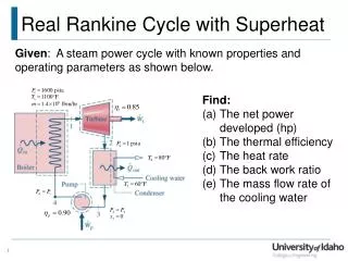
Carnot Is Not Practical • Why is the Carnot Vapor Power Cycle impractical ? • Most pumps do not handle vapor-liquid mixtures well • Pumps that do are more expensive and less efficient. • Turbines do not work well with low quality • Quality must be greater than 90% at the outlet • This is difficult to achieve without superheating in the reboiler • Using strictly isothermal heating prevents… • Subcooled liquid feed to the boiler which would make the pump more efficient • Superheating in the boiler effluent which would increase turbine effluent quality Baratuci ChemE 260 May 16, 2005
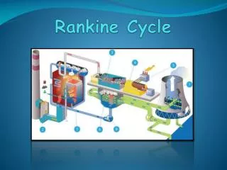
The Rankine Cycle • A practical vapor power cycle • Minimizes cavitation problems in the pump • Allows for the possibility of superheating in the boiler • The Rankine Cycle • Step 1-2: Boiler Heat added at constant pressure • Step 2-3 Turbine Isentropic expansion • Step 3-4: Condenser Heat rejected at constant pressure • Step 4-1: Pump Isentropic compression • Internally Reversible • External irreversibility due to heat transfer through a finite temperature difference in the boiler Baratuci ChemE 260 May 16, 2005
TS Diagram Baratuci ChemE 260 May 16, 2005
Cavitation Baratuci ChemE 260 November 23, 2004
Efficiency & Boiler Pressure • WSh • QH • th Baratuci ChemE 260 May 16, 2005
Efficiency & Condenser Pressure • WSh • QH: same • th Baratuci ChemE 260 May 16, 2005
Next Class … • CIDR Focus Group Interview • After that … Problem Session • And then … • Improvements to the Rankine Cycle • Superheat the turbine feed • Pump to supercritical pressure • Use a two-stage turbine with a reheater between stages • Use regeneration with a two-stage turbine and a two-stage pump • Use two vapor power cycles to cover a wider T range • Non-ideal behavior in vapor power cycles • Boilers and condensers cannot operate at constant P because of friction • Turbines and pumps are neither adiabatic nor internally reversible. • Pump feed must be subcooled to avoid cavitation. Baratuci ChemE 260 May 16, 2005