Download
1 / 63
630 likes | 646 Views
Explore the architectural concepts and structural systems of the CEE 222 project in San Francisco, integrating creative open spaces for collaboration amidst a beautiful campus setting.

E N D
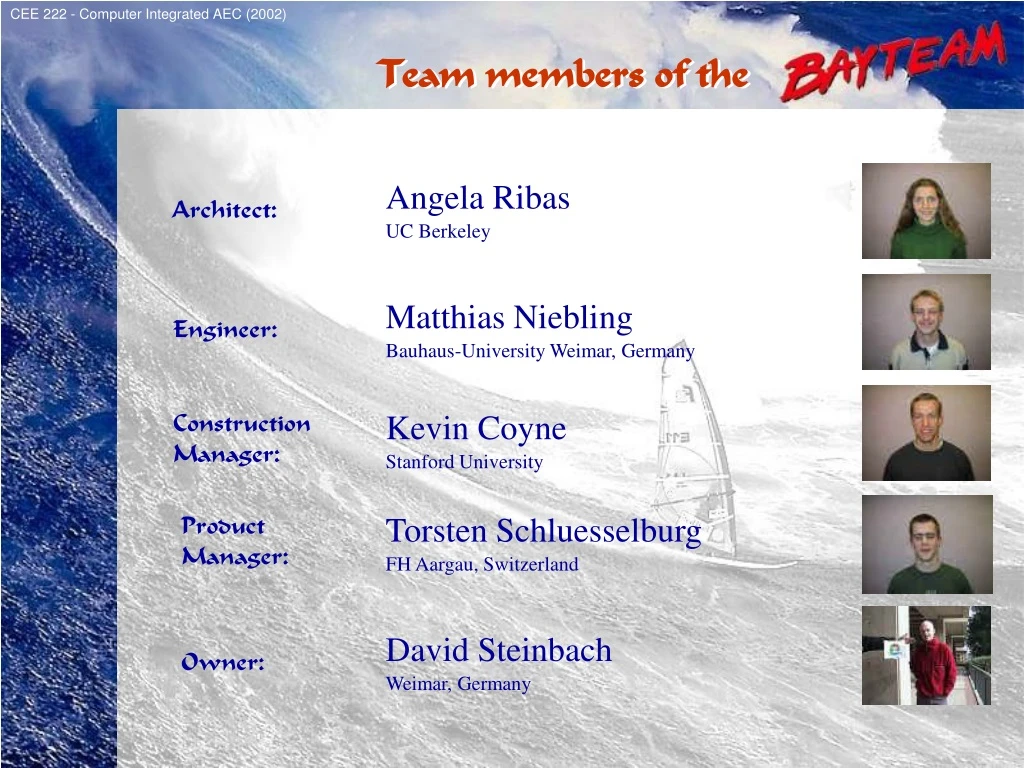
TeamMembers CEE 222 - Computer Integrated AEC (2002) Team members of the Team members of the Angela Ribas Architect: UC Berkeley Matthias Niebling Engineer: Bauhaus-University Weimar, Germany Construction Manager: Kevin Coyne Stanford University Product Manager: Torsten Schluesselburg FH Aargau, Switzerland David Steinbach Owner: Weimar, Germany
Location CEE 222 - Computer Integrated AEC (2002) • SURROUNDING: • GOLDEN GATE PARK • RESIDENTIAL NEIGHBORHOOD • HILL AREA (HUGE GREEN AREA) CAMPUS LOCATION CAMPUS LOCATION • BAY AREA / CITY OF SAN FRANCISCO • UNIVERSITY OF SAN FRANCISCO • MAIN CAMPUS AT FULTON STREET
CEE 222 - Computer Integrated AEC (2002) CAMPUS VIEW CAMPUS VIEW N Map
CEE 222 - Computer Integrated AEC (2002) SURROUNDING BUILDINGS SURROUNDING BUILDINGS SITE MAP Textures
CEE 222 - Computer Integrated AEC (2002) SITE SITE N PANORAMIC VIEW • FLAT GROUND • FACING FULTON STREET SITE MAP Building location
A_First concept CEE 222 - Computer Integrated AEC (2002) FIRST ARCHITECTURAL CONCEPT FIRST ARCHITECTURAL CONCEPT FOREST “AN OPEN AND FRIENDLY SPACE WHERE PEOPLE CAN INTERACT” CORE VIEW Concept
CEE 222 - Computer Integrated AEC (2002) FIRST ARCHITECTURAL CONCEPT FIRST ARCHITECTURAL CONCEPT FIRST FLOOR PLAN Plan
CEE 222 - Computer Integrated AEC (2002) FIRST ARCHITECTURAL CONCEPT FIRST ARCHITECTURAL CONCEPT BASEMENT Plan
CEE 222 - Computer Integrated AEC (2002) FIRST ARCHITECTURAL CONCEPT FIRST ARCHITECTURAL CONCEPT SECOND FLOOR Plan
CEE 222 - Computer Integrated AEC (2002) FIRST ARCHITECTURAL CONCEPT FIRST ARCHITECTURAL CONCEPT THIRD FLOOR Plan
CEE 222 - Computer Integrated AEC (2002) FIRST ARCHITECTURAL CONCEPT FIRST ARCHITECTURAL CONCEPT N C B B A A C SECTION AA SECTION BB SECTION CC Sections
CEE 222 - Computer Integrated AEC (2002) FIRST ARCHITECTURAL CONCEPT FIRST ARCHITECTURAL CONCEPT N SOUTH FACADE SOUTH FACADE NORTH FACADE NORTH FACADE EAST FACADE TOP VIEW Elevations WEST FACADE
A1_E_SOLUTION1 CEE 222 - Computer Integrated AEC (2002) STRUCTURAL SYSTEM STRUCTURAL SYSTEM
Loading assumptions CEE 222 - Computer Integrated AEC (2002) • First floor corridors / Stairs / Lobbies • Storage • Auditorium, Offices • Classrooms • Corridors above first floor • Finishes, Lights • HVAC installation (ducts, etc) • Partition walls • Wind load • RAIN LOAD 100 psf 125 psf 30 psf 10 psf 13 psf 50 psf 80 psf 20 psf 40 psf 5 psf 1.92 kN/m² 4.79 kN/m² 6.00 kN/m² 3.83 kN/m² 2.40 kN/m² 1.44 kN/m² 0.48 kN/m² 0.24 kN/m² 0.96 kN/m² 0.64 kN/m² STRUCTURAL SYSTEM STRUCTURAL SYSTEM DEAD LOADS: LIVE LOADS: LATERAL LOADS: Load Assumptions
Concrete Walls CEE 222 - Computer Integrated AEC (2002) Concrete walls STRUCTURAL SYSTEM STRUCTURAL SYSTEM Typical element sizes: Concrete walls: 12“ Structural elements
Girders CEE 222 - Computer Integrated AEC (2002) Concrete walls Girders Possible sections of a column 16“ 15“ typical column / girder connection STRUCTURAL SYSTEM STRUCTURAL SYSTEM Structural elements
2 former Solutions CEE 222 - Computer Integrated AEC (2002) Concrete walls Solution 1 Girders Solution 2 STRUCTURAL SYSTEM STRUCTURAL SYSTEM • Composite floor deck • Bays of 30 x 30 ft • Advantage: only 4 columns needed • Steel Frame Structure • Spans of 15 ft (concrete elements) and • 30 ft (steel frames) • Advantage: slab can be thin (reduction of dead loads) Former solutions
Typical element sizes CEE 222 - Computer Integrated AEC (2002) Concrete walls Girders • only 4 columns Secondary Beams • reduced slab thickness • Small Girders: 12“ (HEB 280) • Large Girders: 15“ (HEB 360) Columns (in basement): ø 16“ with a steel thickness of 1/3“ STRUCTURAL SYSTEM STRUCTURAL SYSTEM Most economic compromise: takes the advantages of both structural solutions Typicalelement sizes: • Concrete walls: 12“ • Slab: Compositefloor deck, total height: 4 ¾“ • Secondary beams: 8“ (HEA 200) Typical element sizes
Gravity Load Path1 CEE 222 - Computer Integrated AEC (2002) Concrete walls Girders Secondary Beams Gravity Load Path STRUCTURAL SYSTEM STRUCTURAL SYSTEM Gravity Load Path1
Gravity Load Path2 CEE 222 - Computer Integrated AEC (2002) Concrete walls Girders Secondary Beams Gravity Load Path STRUCTURAL SYSTEM STRUCTURAL SYSTEM
Gravity Load Path3 CEE 222 - Computer Integrated AEC (2002) Concrete walls Girders Secondary Beams Gravity Load Path STRUCTURAL SYSTEM STRUCTURAL SYSTEM
Gravity Load Path4 CEE 222 - Computer Integrated AEC (2002) Concrete walls Girders Secondary Beams Gravity Load Path STRUCTURAL SYSTEM STRUCTURAL SYSTEM
Gravity Load Path5 CEE 222 - Computer Integrated AEC (2002) Gravity Load Path STRUCTURAL SYSTEM STRUCTURAL SYSTEM
Foundation MainBuilding CEE 222 - Computer Integrated AEC (2002) Line loads Column loads STRUCTURAL SYSTEM STRUCTURAL SYSTEM Foundation will be: • a ground plate with a height of 15“ • at the positions of concentrated loads (columns): strengthening of the ground plate up to 24“ Foundation – Main Building
Foundation Auditoroium CEE 222 - Computer Integrated AEC (2002) Line loads STRUCTURAL SYSTEM STRUCTURAL SYSTEM Foundation will be: • a ground plate with a height of 15“ • at the positions of concentrated loads (columns): strengthening of the ground plate up to 24“ • the floor of the auditorium is declined. • using a stepping instead of declination -> horizontal loads (out of gravity loads) are avoided Foundation - Auditorium
Lateral Load Path Left CEE 222 - Computer Integrated AEC (2002) Concrete walls Lateral Load Paths STRUCTURAL SYSTEM STRUCTURAL SYSTEM Symmetrical plan: • no additional moment occurs
Lateral Load Path Right CEE 222 - Computer Integrated AEC (2002) Concrete walls N • can be compensatet by two normal forces N e S M N Lateral Load Paths STRUCTURAL SYSTEM STRUCTURAL SYSTEM Asymmetrical plan: • additional moment (M=N·e)
Outside Wall CEE 222 - Computer Integrated AEC (2002) • it is necessary to build a moment resisting frame structure Lateral Load Paths STRUCTURAL SYSTEM STRUCTURAL SYSTEM Outside concrete walls: • do not act as a slab because of number of openings • high amount of reinforcement is needed
A1_C_Slide1 CEE 222 - Computer Integrated AEC (2002) CONSTRUCTION SITE PLAN CONSTRUCTION SITE PLAN Existing Buildings Site Access (Fulton) Project Office Material Laydown & Storage Crane Building Perimeter Site Perimeter Site plan
A1_C_Slide2 CEE 222 - Computer Integrated AEC (2002) CONCEPT #1: CONSTRUCTION CONCEPT #1: CONSTRUCTION • EXCAVATION: • 18’ Hard Strata Excavation – No retaining wall necessary • FOUNDATION: • Poured Reinforced Concrete Mat Slab w/ Column Footings • SUPERSTRUCTURE A: • Reinforced Concrete Moment Frame • Cast-in-Place Reinforced Concrete Shear Walls • Cast-in-Place Composite Concrete/Steel Floor System • SUPERSTRUCTURE B: • Steel Moment Frame • Cast-in-Place Composite Concrete/Steel Floor System • EXTERIOR FACADE: • Concrete and Glass Curtain Wall System Materials and Methods
A1_C_Slide3 CEE 222 - Computer Integrated AEC (2002) CONCEPT #1: COST CONCEPT #1: COST Structural Solution #1: Structural Solution #2: • Concrete Moment Frame • Concrete Shear Walls • Steel Moment Frame • Concrete Shear Walls Total Cost = $6,070,122 Per S.F. = $164.06 Total Cost = $5,892,664 Per S.F. = $159.26
A1_C_Slide2 CEE 222 - Computer Integrated AEC (2002) CONCEPT #1: SCHEDULE CONCEPT #1: SCHEDULE Schedule Duration = 9 months Start: 9/20/2015 – End: 7/7/2016 Schedule Duration = 9 months Start: 9/20/2015 – End: 7/7/2016 MILESTONE #1: 3/01/16 – Foundation Complete MILESTONE #2: 5/10/16 – Shell Complete MILESTONE #3: 9/30/16 – Move-In Conceptual Schedules
A_Second concept CEE 222 - Computer Integrated AEC (2002) • Plaza • Suspended box • Open auditorium below • “The crane” - A / E idea • Suspended auditorium • very expensive • Bridge idea for suspension • Owner requested round forms • “The bridge curve” • access and circulation issues SECOND ARCHITECTURAL CONCEPT SECOND ARCHITECTURAL CONCEPT CONCEPTUAL IDEAS Progress
CEE 222 - Computer Integrated AEC (2002) SECOND ARCHITECTURAL CONCEPT SECOND ARCHITECTURAL CONCEPT PLAZA “A PLAZA SURROUNDED BY WATER” Concept
CEE 222 - Computer Integrated AEC (2002) SECOND ARCHITECTURAL CONCEPT SECOND ARCHITECTURAL CONCEPT FIRST FLOOR PLAN Plan
CEE 222 - Computer Integrated AEC (2002) SECOND ARCHITECTURAL CONCEPT SECOND ARCHITECTURAL CONCEPT BASEMENT PLAN Plan
CEE 222 - Computer Integrated AEC (2002) SECOND ARCHITECTURAL CONCEPT SECOND ARCHITECTURAL CONCEPT SECOND FLOOR PLAN Plan
CEE 222 - Computer Integrated AEC (2002) SECOND ARCHITECTURAL CONCEPT SECOND ARCHITECTURAL CONCEPT THIRD FLOOR PLAN Plan
CEE 222 - Computer Integrated AEC (2002) SECOND ARCHITECTURAL CONCEPT SECOND ARCHITECTURAL CONCEPT N A A S / N FACADE SECTION AA E / W FACADE EAST / WEST FACADE SOUTH / NORTH FACADE TOP VIEW Section / Elevations
A2_E_SOLUTION1 CEE 222 - Computer Integrated AEC (2002) Architectural sketch • Width: 100 ft • Length: 145 ft Engineering model STRUCTURAL SYSTEM #1 STRUCTURAL SYSTEM #1
Constraints CEE 222 - Computer Integrated AEC (2002) • as well as concrete walls in the core (Elevators, Restrooms) STRUCTURAL SYSTEM #1 STRUCTURAL SYSTEM #1 Solution 1 • the whole building is based on 4 large columns at the corners • an additional 4 columns in the core
Gravital Structure CEE 222 - Computer Integrated AEC (2002) Girders Secondary Beams • Additionally, secondary beams will be used to reduce the span of the slab STRUCTURAL SYSTEM #1 STRUCTURAL SYSTEM #1 In each slab there will be 4 large girders • to collect gravity loads and transport them to the framework and the core columns Gravity Structure
Framework CEE 222 - Computer Integrated AEC (2002) Girders Secondary Beams STRUCTURAL SYSTEM #1 STRUCTURAL SYSTEM #1 Realizing the large span by a huge framework: • to collect gravity loads and transport lateral loads • to reduce deformation of the slabs Gravity Structure
Element sizes CEE 222 - Computer Integrated AEC (2002) Girders Secondary Beams • Small Girders: 14“ (HEB 340) • Large Girders: 24 1/2“ (HEM 600) STRUCTURAL SYSTEM #1 STRUCTURAL SYSTEM #1 Framework Typical Element sizes: • Slab: Composite floor deck, total height: 4 ¾“ (Span ~11ft) • Secondary beams: 8“ (HEA 200) • Core Columns: 20“ x 20“ • Outside Columns: 40“ x 40“ (Assumption) Typical element sizes
GravityLoadPath CEE 222 - Computer Integrated AEC (2002) Gravity Load Path STRUCTURAL SYSTEM #1 STRUCTURAL SYSTEM #1 Forces are transported: • from secondary beams to the girders • from girders to the outside framework and the inner core • by vertical elements into the ground
Lateral Structure CEE 222 - Computer Integrated AEC (2002) • Note – detailed calculations will need to be completed to determine the feasibility of this solution (due to massive framework) STRUCTURAL SYSTEM #1 STRUCTURAL SYSTEM #1 Stiffening the inside of the box by EBF‘s (eccentric braced frames): • Advantage – in case of an earthquake, EBF‘s can absorb some of energy Lateral Resisting Structure
LateralLoadPath_Left CEE 222 - Computer Integrated AEC (2002) Lateral Load Paths STRUCTURAL SYSTEM #1 STRUCTURAL SYSTEM #1 Symmetrical plan: • no additional moments occur
LateralLoadPath_Top CEE 222 - Computer Integrated AEC (2002) Lateral Load Paths STRUCTURAL SYSTEM #1 STRUCTURAL SYSTEM #1 Symmetrical plan: • no additional moments occur
Foundation Columns CEE 222 - Computer Integrated AEC (2002) • the core columns are supposed to be thinner and more ductile, allowing for deformation in case of an earthquake • these two columns are connected to the wall of the auditorium STRUCTURAL SYSTEM #1 STRUCTURAL SYSTEM #1 Foundation of the columns is critical because of seismic issues: • the outside columns must be able to rock -> base isolation system Foundation
FoundationBasement CEE 222 - Computer Integrated AEC (2002) STRUCTURAL SYSTEM #1 STRUCTURAL SYSTEM #1 Foundation of the basement: • will be a ground plate • in the core, a strengthening of the ground plate becomes necessary (columns) Foundation