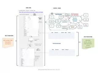
CAL Meta-Model An Application
CAL Meta-Model An Application. Applications of the meta-model means making texture choices. How to represent Behavior Specifications System models Components Interfaces Relationships between elements. Conceptual System Model. *. Conceptual System Model Texture. Behavior

CAL Meta-Model An Application
E N D
Presentation Transcript
Applications of the meta-model means making texture choices. • How to represent • Behavior Specifications • System models • Components • Interfaces • Relationships between elements
Conceptual System Model * Conceptual System Model Texture Behavior Specification CAL – CSM
Abstract System Model * Abstract Component Abstract System Model Texture * Abstract Interface * <<localization>> Abstract Component Interface Abstract Component Specification <<localization>> CAL – ASM
Logical System Model Logical Software Model Logical System Model Texture Logical Environment Model <<localization>> <<localization>> * Logical Software Model Texture Logical Environment Model Texture Logical Interface * * Operating Environment Model Logical Component * Run-Time Services Model Hardware Model CAL – LSM
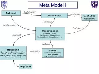
Arch – Behavior Specification • Behavior Specifications are captured using use cases (policy) • Format of use case is defined in a template (pattern) • Each use case must contain at least one main scenario (policy) • Each use case may have any number of alternatives (policy) • All alternatives must be a deviation from the main scenario (policy) • Use cases may only be related by an include relationship which has the typical interpretation (policy)
Arch – Visual Representations • Relationships between use cases and between actors and use cases are illustrated through UML Use Case diagrams
Example System – Healthcare Mgmt System • Use Case Example Use Case : Update Test Results Main Scenario 1. Technician submits results for a test. 2. System determines the test results require no further action. 3. System updates patient info with test results. Alternative : Tests imply prescription 2. System determines the test requires a prescription. 3. Include Process Prescription. Alternative : Tests imply prescription and follow-up visit 2. System determines the test requires a prescription and follow-up visit. 3. System requests next available appointment for patient. 4. System adds appointment to patient’s info. 5. Include Process prescription.
View Patient Info Update Test Results Schedule Visit Order Prescription Schedule Test Process Prescription Example System – Healthcare Mgmt • Use Case Diagram Healthcare Management System Doctor Patient <<include>> Technician <<include>>
Abstract System Model * Abstract Component Abstract System Model Texture * Abstract Interface * <<localization>> Abstract Component Interface Abstract Component Specification <<localization>> CAL – ASM
<<abstract component>> ComponentName <<abstract component interface>> <<abstract component specification>> ComponentName_Interface ComponentName_Specification <<abstract component>> ComponentName Arch – Rep. of an Abstract Component
<<abstract interface>> InterfaceName <<abstract interface>> InterfaceName <<in>> inMessageName1(<parameter list>) . . . <<in>> inMessageNamek(<parameter list>) <<out>> outMessageName1(<parameter list>) . . . <<out>> outMessageNamej(<parameter list>) Arch – Rep. of an Abstract Interface
Arch – Relationships between the AC and AI • Abstract Components either “use” or “provide” an Abstract Interface • The relationship is represented by a dependency stereotyped by either • <<use>> • <<provide>>
<<abstract component>> <<provide>> <<abstract interface>> ComponentName InterfaceName <<abstract component>> <<use>> <<abstract interface>> ComponentName InterfaceName Arch – Relationships between the AC and AI
Arch – Relationships between the Abstract Component and Abstract Interface • Providers generate all “out” messages and receive “in” messages • Users generate all “in” messages and receive all “out” messages
Abstract System Model * Abstract Component Abstract System Model Texture * Abstract Interface <<localization>> * Abstract Component Interface Abstract Component Specification <<localization>> Arch – Realizing localization of the Abstract Interface
DataClass <<abstract interface>> <<abstract interface>> InterfaceName InterfaceName <<use>> <<duplicate>> <<abstract component>> <<abstract component specification>> ComponentName ComponentName_Specification InterfaceName DuplicateDataClass Arch – <<use>> localization
DataClass <<abstract interface>> <<abstract interface>> InterfaceName InterfaceName <<provide>> <<abstract component>> <<abstract component specification>> ComponentName ComponentName_Specification InterfaceName DataClass <<abstract component interface>> ComponentName_Specification Contains a collection of textual descriptions and diagrams that describe what interfaces are provided and how
Arch – Describing Abstract Component Interactions • Interactions between components are captured using sequence diagrams • Asynchronous communication should be used • Sequence diagrams are constrained by the following policy: • Let C be an abstract component, I be an Abstract Interface. Let c be an instance of the component container of C and m be a message defined in I. Then • c may be a target for m if C provides I and m is stereotyped as <<in>> or <<inout>>, or C uses I and m is stereotyped as <<out>> or <<inout>>. • c may be a source for m if C uses I and m is stereotyped as <<in>> or <<inout>>, or C provides I and m is stereotyped as <<out>> or <<inout>>.
Arch – Demonstrating the Realization of a CSM by an ASM • For each use case, a class diagram of the following form must be created <<Use case name>> Is realized by <<abstract component>> <<abstract interface>> <<component name>> <<interface name>> <<use>> and/or <<provide>> 1 or more 0 or more
Arch – Demonstrating the Realization of a CSM by an ASM • Each use case will also have one or more sequence diagrams associated to it capturing the interaction between components that meets the use case
Example System – Healthcare Mgmt System <<abstract interface>> <<provide>> <<abstract component>> <<use>> PatientInfoIF PatientManager <<abstract component>> <<provide>> <<use>> <<provide>> HealthcareManagementSystem <<abstract interface>> UpdateResultsIF <<use>> <<abstract interface>> <<use>> MessageIF <<abstract interface>> <<use>>, <<provide>> ScheduleTestIF <<use>> <<abstract interface>> <<use>> AppointmentIF <<provide>> <<use>> <<use>> <<abstract component>> TestManager <<use>> <<abstract interface>> <<use>> PrescriptionIF <<abstract interface>> ScheduleNextAvailIF <<use>> <<abstract component>> <<provide>> InsuranceManager <<provide>> <<provide>> <<abstract component>> <<provide>> ScheduleManager <<abstract interface>> <<use>> CoverageRequestIF <<abstract component>> PrescriptionManager
Example System – Healthcare Mgmt System Update Test Results <<abstract interface>> PrescriptionIF is realized by <<in>> scheduleNextAvailAppt (patientId : int) <<abstract component>> HealthcareManangementSystem <<abstract component>> <<use>> <<use>>, <<use>> <<provide>> TestManager <<abstract interface>> PrescriptionIF <<use>> <<use>> <<abstract interface>> <<abstract interface>> <<provide>> UpdateResultstIF UpdateResultsIF <<in>> updateResults(patientId : int, testInfo : TestInfo) <<use>> <<abstract component>> ScheduleManager <<abstract interface>> MessageIF TestInfo <<abstract interface>> <<provide>> PrescriptionIF <<provide>> <<abstract component>> <<provide>> PatientManager <<abstract interface>> PrescriptionIF <<in>>prescribe (pid: int, preInfo : PrescriptionInfo) <<abstract interface>> MessageIF <<in>> addMessage (patientId : int, msg : PatientMessage) PrescriptionInfo PatientMessage
Update Test Results : Tests Imply Prescription and Follow-up Visit :HealthcareManangementSystem :TestManager :PatientManager :ScheduleManager :PrescriptionManager updateResults(patientId, testInfo) updateResults (patientId, testInfo) Tech submits test results scheduleNextAvailAppt (patientId) addMsg (patientId, message) Begin Process Prescription use case prescribe (patientId, prescripInfo) Example System – Healthcare Mgmt System
Logical System Model Logical Software Model Logical System Model Texture Logical Environment Model <<localization>> <<localization>> * Logical Software Model Texture Logical Environment Model Texture Logical Interface * * Operating Environment Model Logical Component * Run-Time Services Model Hardware Model CAL – LSM
Arch – LSM • We do not define an LSM Texture at this time • LEM Texture consists of the following policies • The language implementation will be Java using SDK 1.5 • The development environment will be Eclipse • OEM is not needed as we are using pure Java • This leaves just the LSWM • i.e., Logical Components, Logical Interfaces, etc
Arch - Representation of a Logical Component <<logical component>> ComponentName <<logical component interface>> <<logical component specification>> ComponentName_Interface ComponentName_Specification <<logical component realization>> ComponentName_Realization <<logical component>> ComponentName ComponentName
Arch – Representation of a Logical Interface • We are using Java – there is no “in” or “out” concept • We represent it as a package with a stereotype <<logical interface>> • The package has two classes • <interface>_in the “in” messages • <interface>_out the “out” messages • It may also contain data classes
Time <<abstract interface>> Data DataIF <<abstract interface>> DataIF <<in>> requestData() <<out>> newData(data : Data) <<inout>> timeSync(time : Time) <<logical interface>> Data DataIF Time DataIF_in DataIF_out newData(data : Data) : void timeSync(time : Time) : void requestData() : void timeSync(time : Time) : void Arch – Realizing an Abstract Interface by an Logical Interface
<<logical component>> <<provide>> <<logical interface>> ComponentName InterfaceName <<logical component>> <<use>> <<logical interface>> InterfaceName ComponentName Arch – Relationships between Logical Component and Logical Interface • Similar to that of AC and AI
Arch – Relationships between the Logical Component and Logical Interface • Providers generate all “out” messages and receive “in” messages • Users generate all “in” messages and receive all “out” messages
<<duplicate>> DataClass <<logical interface>> InterfaceName_out InterfaceName <<use>> InterfaceName_in <<logical component>> <<logical component specification>> ComponentName ComponentName_Specification InterfaceName_SenderAsUser InterfaceName_ReceiverAsUser DuplcateDataClass Arch – <<use>> Localization
<<duplicate>> DataClass <<logical interface>> InterfaceName_in InterfaceName <<provide>> InterfaceName_out <<logical component>> <<logical component specification>> ComponentName ComponentName_Specification <<logical component interface>> InterfaceName_SenderAsProvider ComponentName_Interface InterfaceName_ReceiverAsProvider DuplicateDataClass Contains a collection of textual descriptions and diagrams that describe what interfaces are provided and how Arch – <<provide>> Localization
Arch – Completing the Logical Component • Logical Component Specification has • “Component container” • Collection of sender/receiver classes • These relate as follows • Component container contains a single instance of each sender/receiver • Component container contains an instance of a class that encapsulates the component’s behavior • It’s abstract • Name <component name>Behavior • Each receiver class is associated to the component behavior class • When a message arrives is calls “addMessage()” to place the message in the component behavior object’s queue • The component behavior class has an operation to handle every possible message • handle_<interface name>_<message name> • The behavior class is associated to every sender class
PrescriptionIF_in scheduleNextAvailAppt() <<provide>> <<logical component>> <<logical interface>> ScheduleManager ScheduleNextAvail;F <<provide>> <<use>> <<logical interface>> AppointmentIF <<logical interface>> MessageIF AppointmentIF_in AppointmentIF_out MessageIF_in appointmentRequest() success() failure() addMessage () Example System – Healthcare Mgmt System
Example System – Healthcare Mgmt System <<logical component specification>> ScheduleManager MessageIF_SenderAsUser ScheduleNextAvailIF_ReceiverAsUser addMessage () scheduleNextAvailAppt() AppointmentIF_SenderAsProvider AppointmentIF_ReceiverAsProvider success() failure() appointmentRequest() <<abstract>> ScheduleManagerBehavior addMessage() #process_ScheduleNextAvailIF_scheduleNextAvailAppt() #process_AppointmentIF_appointmentRequest()
:ScheduleNextAvailIF_ReceiverAsProvider :ScheduleManager_Behavior :MessageIF_SenderAsUser scheduleNextAvailAppt() addMessage() handle_ScheduleNextAvailApptIF_scheduleNextAvailAppt() Eventually message is ready to be handled addMessage() Example System – Healthcare Mgmt System