MICE phase III
190 likes | 322 Views
This report discusses the ongoing analysis from the MICE Phase III meeting, focusing on the integration of two back-to-back tracker solenoids without RF cavities. It examines the innovative approach to cross-calibrate the solenoids and tracking systems, targeting a 1% measurement accuracy of emittance change. The study includes the use of ICOOL simulations and explores the implications of coil current optimization on cooling performance, particularly in the context of different absorber materials and configurations. The findings also consider the significance of match coil currents and their influence on achieving symmetric beta functions.

MICE phase III
E N D
Presentation Transcript
MICE phase III M. Apollonio, J. Cobb (Univ. of Oxford) MICE Analysis Meeting
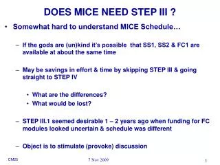
work in progress! • PHASE III • Two back to back tracker solenoids, no RF cavities • Never studied in any detail • Assumption: step 3 can be used to: • Cross-calibrate solenoids and tracking • Demonstrate capability of measuring an emittance change to 1% • 1st possibility of observing cooling with solid absorber(s) • Simulation • ICOOL code • evbeta: • numerical solution of optical functions differential equations MICE Analysis Meeting
U.Bravar’s study on matching revisited • Naive approach: • take M. Green’s currents for step 6 w.o. cooling channel (just so) but … 1st step: MATCHING Step VI Step III • Not just a matter of taking the whole experiment and put the two spectrometers closer (~800 mm, to be checked) • Coil matchingis an important issue !!! • Solenoids will operate differently in step 3 from steps [4,6] MICE Analysis Meeting
If you keep the same coil currents you end up into troubles … Asymmetric beta functions Solution: optimize the match coil currents i.o.t. get a symmetric (well behaved) beta function b (m) vacuum flip mode z (m) MICE Analysis Meeting
evbeta + MINUIT Constraints used: b = 33cm symmetrical in the solenoid regions a = 0 in the solenoid regions == b flat Force b to be ~ 60 cm in the middle of the apparatus Find the new coil currents: Variation with respect to M. Green‘s starting currents DI/I(min) ~ -30%, DI/I(max) ~ +7% CAVEAT: check current densities!!! FLIP MODE (fm), NON-FLIP MODE (nfm) MICE Analysis Meeting
M.Green file ‘just so’ (no coil currents optimization) 1 -6.007 0.110 0.258 0.326 -145.400 2 -5.848 1.294 0.258 0.280 -146.900 3 -4.507 0.110 0.258 0.320 -136.800 4 -4.150 0.197 0.258 0.284 -161.340 5 -3.710 0.198 0.258 0.304 -147.550 6 -2.712 0.198 0.258 0.304 147.550 7 -2.271 0.197 0.258 0.284 161.340 8 -1.827 0.110 0.258 0.320 136.800 9 -1.670 1.294 0.258 0.280 146.900 10 -0.327 0.110 0.258 0.326 145.400 flip mode non flip mode coil current files after optimization 1 -6.007 0.110 0.258 0.326 -145.400 2 -5.848 1.294 0.258 0.280 -146.900 3 -4.507 0.110 0.258 0.320 -136.800 4 -4.150 0.197 0.258 0.284 -116.717 5 -3.710 0.198 0.258 0.304 -159.676 6 -2.712 0.198 0.258 0.304 -159.676 7 -2.271 0.197 0.258 0.284 -116.717 8 -1.827 0.110 0.258 0.320 -136.800 9 -1.670 1.294 0.258 0.280 -146.900 10 -0.327 0.110 0.258 0.326 -145.400 1 -6.007 0.110 0.258 0.326 -145.400 2 -5.848 1.294 0.258 0.280 -146.900 3 -4.507 0.110 0.258 0.320 -136.800 4 -4.150 0.197 0.258 0.284 -112.539 5 -3.710 0.198 0.258 0.304 -157.036 6 -2.712 0.198 0.258 0.304 157.036 7 -2.271 0.197 0.258 0.284 112.539 8 -1.827 0.110 0.258 0.320 136.800 9 -1.670 1.294 0.258 0.280 146.900 10 -0.327 0.110 0.258 0.326 145.400 MICE Analysis Meeting
After finding the new -matched- currents we can run ICOOL sim. + ecalc9 For several materials In this study: 2 slabs of different materials soon after the first spectro and just before the second spectro Study with central absorber still to be done Li, LiH, C, Polyethilene, Be (NO Liq. H) Thickness chosen in order to ensure a total 13% reduction in p (thicker slabs result in a funny beta behavior) Withdifferentvalues ofinitial emittance Plot of de/e Cooling of 5% visibile in FLIP-mode (less cooling in NON FLIP-mode) 2nd step: study of cooling performances MICE Analysis Meeting
Sketch of absorbers position in phase III absorbers MICE Analysis Meeting
Parameters used in simulation Pz=207 MeV/c with a spread of 10% Initial emittances ranging from 0.1 to 1.0 (cm rad) 10000 generated muons per point (i.e. initial emittance) Lost muons: worse cases at high initial e (=1.0 cm rad) 4% (LiH, C, non flip mode) 3% (C, flip mode) MICE Analysis Meeting
FLIP mode (in vacuum) • Evbeta calculation • ICOOL simulation b (m) Bz (T) Z (m) Z (m) MICE Analysis Meeting
Non FLIP mode (in vacuum) • Evbeta calculation • ICOOL simulation b (m) Bz (T) MICE Analysis Meeting Z (m) Z (m)
FLIP mode (LiH) • Initial emittances: • e=0.2 cm rad • e =0.25 cm rad • e =0.3 cm rad • e =0.6 cm rad • Points taken at several initial emittance values • Emittance ‘measured’ at the end of the II tracker Bz (T) b (m) Z (m) Z (m) De/e (%) Z (m) Dp/p (%) Z (m) MICE Analysis Meeting
Non FLIP mode • Initial emittances: • e=0.2 cm rad • e =0.25 cm rad • e =0.3 cm rad • e =0.6 cm rad Bz (T) b (m) Z (m) Z (m) De/e (%) Z (m) Dp/p (%) Z (m) MICE Analysis Meeting
Flip mode Non-flip mode LiH, Li, Be, CH, C De/e (%) De/e (%) e (cm rad) e (cm rad) 0.22, 0.26, 0.38, 0.41, 0.57 (cm rad) 0.22, 0.25, 0.35, 0.4, 0.6 (cm rad) equilibrium emittances MICE Analysis Meeting
J. Cobb emittance variation initial emittance MICE Analysis Meeting
NB: cooling of large emittance beam is less than expected for a given Dp/p • De/e = Dp/p * (1-e(eqm)/e) • Should reach Dp/p asymptotically for e oo • Worse behaviour in NON-FLIP mode • Investigate by removing absorbers in ICOOL • See 2-3% growth of emittance for large emittance beams w.o. absorbers • We know from UB and BP et al that norm. emittance is NOT conserved in a drift • |B| is low in drift region between 2 solenoids Emittance growth • No simple model for this (unsatisfactory) MICE Analysis Meeting
ei=0.3 cm rad ei=0.2 cm rad ei=1.0 cm rad ei=0.6 cm rad ei=0.1 cm rad Emittance growth in vacuum: NO ABSORBERS MICE Analysis Meeting
De/e (%) e (cm rad) NO absorbers: emittance growth in vacuum MICE Analysis Meeting
Conclusions (very tentative) • Step 3 needs a lot more study • Simple demonstration of 1% emittance measurement capability of MICE may not be easy/possible in step III (i.e. not as easy as perhaps expected) • It could be possible to observe some cooling with LiH or Li or Be absorbers, but may need correction from MC (unpleasant) • To DO list • Find optimum/better matches • Investigate emittance growth • Try placing a central absorber • Optmize thickness for absorbers MICE Analysis Meeting