Download

1 / 42
420 likes | 572 Views
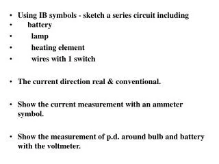
Using IB symbols - sketch a series circuit including battery lamp heating element wires with 1 switch The current direction real & conventional . Show the current measurement with an ammeter symbol. Show the measurement of p.d . around bulb and battery with the voltmeter.

E N D
Using IB symbols - sketch a series circuit including • battery • lamp • heating element • wires with 1 switch • The current direction real & conventional. • Show the current measurement with an ammeter symbol. • Show the measurement of p.d. around bulb and battery with the voltmeter.
Series CircuitsSeries circuits are a chain of components connected in a circle providing only 1 path for current.
By conservation of charge, & because there is only one route, the current (I) is the same everywhere.I1 = I2 = I3 …1, 2, 3 represent circuit components.
Resistance on a series circuit.As more resistors are added Rtot increases.The total/ equilvalent resistance is: R1 + R2+ R3 = Req.
Voltage around resistors.The eq V is the sum of the p.d.’s across each resistor on the circuit.V1 + V2+ V3 ~ VT.
R1 R2 R3 I Apply Ohm’s Law to individual components on circuit The p.d. or V across each resistor is always: V1 = IR1. V2 = IR2. V3 = IR3. Add each device voltage to find the VT.The eq(total) resistance is the sum. R1+ R2 + R3 = Req.
Since there is only one path for the charges to follow if one conductor (resistor) is disconnected, the circuit is broken. The current flow stops.
Since the devices must share the voltage, as more are added the energy of the charges decreases. The voltage “divides” between resistors.
Energy Supply in Series As you add more cells, the total voltage adds.
Parallel Circuits are connected so that the current reaches a fork or junction & divides.
Since each resistor is connected across the voltage, the voltage is equal everywhere, and equal to the battery voltage.V1 = V2 =V3 = Vtot
Current (I), when the charges reach a junction, they divide. The total current in the circuit = S individual currents in each branch. Itot = I1 + I2 + I3 …Since I = V, & all components have same V, thenR Itot = V + V + V R1 R2 R3.
Resistance is a reciprocal relationship.1/Req = 1/R1 + 1/R2 + 1/R3 …Where Req is the equivalent or total resistance.
As you add resistors, the total equivalent resistance goes down, the total current goes up. The battery or source provides unlimited current!!
Since parallel circuits offer more than one path for the charge to flow, individual parts can be disconnected and charge will still flow through other branches.
Since the voltage is equal on each branch, adding more branches does not reduce the energy each branch receives. Add more bulbs, the others stay bright!
Ammeters measure current & are connected in series on the circuit. Current must flow through them.
Voltmeters measure potential difference & are connected in parallel around the component to be measured.
Ex 1: A 9V battery is connected in series to 2 bulbs: 4W, & 2W. • A) Sketch the diagram with the proper symbols. Show real and conventional current flow direction. B) Sketch a voltmeter reading the voltage at the 2 W resistor and 2 ammeters: one reading the total current and one reading the current at the 4 W resistor.
C) Find the equivalent or total resistance on the circuit.D) Find the total current in the circuit. E) What is the voltage in each resistor?F) What is the current flowing through the 4 W resistor?
Ex 2: A 9V battery is connected in parallel to 2 bulbs: 4W, & 2W. A) Sketch the diagram with the proper symbols. Show real and conventional current flow direction. B) Sketch a voltmeter reading the voltage at the 2 W resistor and 2 ammeters: one reading the total current and one reading the current at the 4 W resistor.
B) Find the equivalent or total resistance on the circuit. C) Find the total current in the circuit. D) What is the voltage in each branch? E) Find the current in each branch.
F) Add the currents from each branch together. How do they relate to the total current?G) Now add a 3 W bulb to the circuit. Recalculate the equivalent resistance.H) Recalculate the current.
Ex: 3 bulbs are in parallel connected to 6V. R1 = 2W, R2 = 3 W, R3 = 4W. Which equation is best to calculate power? Find the power in each bulb.What is relative brightness?What if the 2W is removed? What happens to the brightness of the remaining bulbs?
Hwk Kerrread 137 – 141 do pg147 #1, 4, 6, 8, 9, 12, 13, 15, 22.
Power • The bulb brightness in each resistor is dependant on the power in each resistor. • Since P = VI or P = I2R or P = V2/R, we can calculate the power and deduce the brightness.
Ex: 2 bulbs in series connected to 6V source. R1 = 2W, R2 = 4 W.Find the power in each.What is relative brightness?What if the 2W is removed? What is the power in the remaining bulb?
Ammeters measure current so circuit current must flow through meter. Connect meter in series to measure current.
Voltmeters measure p.d. across resistors so must be connected in parallel.
Kirchoff’s Laws The current entering junction = current exiting. Application of “conservation of charge”.
Total Voltage = sum of all partial voltages on circuit. Application of conservation of energy. 6V 2 V 4V
Fuses – appliances are rated for the power they can safely dissipate.That implies a certain current & voltage (power). Fuses should be chosen to have a current rating a bit higher than the one for which the resistor is designed.
Should fuses and circuit breakers be connected in parallel or in series? Why?
If a 60 W bulb is connected to a 120 V source, the current is: P = VI I = P/V. I = 60 J/s = 0.5 C/s .5A. 120 J/CFuse should be ~ .6-1 A.