Dr. Amir Abramovich
680 likes | 1.06k Views
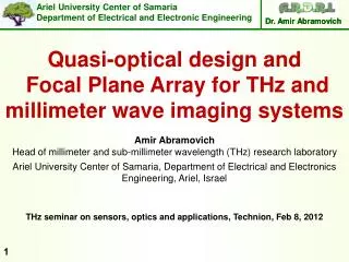
Dr. Amir Abramovich. Quasi-optical design and Focal Plane Array for THz and millimeter wave imaging systems. Amir Abramovich Head of millimeter and sub-millimeter wavelength (THz) research laboratory.

Dr. Amir Abramovich
E N D
Presentation Transcript
Dr. Amir Abramovich Quasi-optical design and Focal Plane Array for THz and millimeter wave imaging systems Amir Abramovich Head of millimeter and sub-millimeter wavelength (THz) research laboratory Ariel University Center of Samaria, Department of Electrical and Electronics Engineering, Ariel, Israel THz seminar on sensors, optics and applications, Technion, Feb 8, 2012
Layout of the talk Introduction. Design parameters and considerations for imaging systems. Imaging ability of focusing systems. Quasi-optical Design approaches for imaging systems. Description of a specific systems and results. DSP and Super-Resolution (SR).
Definitions What is imaging?? • Imaging can be considered to be the process of measuring the radiation arriving from different directions. • Imaging is approximation. What is Quasi-Optics?? Quasi-Optics deals with the propagation of a beam of radiation that is reasonably well collimated but has relatively small dimensions which measured in wavelength, transverse to the axis of propagation
How to obtain an image of a scene (1) • Scanning a single pixel receiver
Imaging mirror FPA Diagonal mirror OPM Collimated beam Object 100 GHz source How to obtain an image of a scene (2) 2) Focal Plane Array (FPA)
How to obtain an image of a scene (3) 3) Interferometric imaging
Passive and active imaging Why passive imaging system? • All Natural objects whose temperatures are above absolute zero emit passive millimeter-wave radiation. • Non invasive • Requires very sensitive and expansive detector and electronics • Usually based on scanning imaging system • Limited dynamic range • Defused scattering from surface. Why Active imaging system? • Requires illumination of the object. • Simpler electronics and better SNR compare to passive • Can be based on direct or heterodyne detection • Can be based on FPA, scanning or interferometric imaging system • Large dynamic range • Specular reflections
Advantages of MMW and THz imaging • Millimeter wavelength propagation is superior to that found in the IR and VIS • Millimeter wavelengths clearly offer better angular resolution • Remote sensing of trace gases.
Sensitivity (1) Passive imaging systems • Very low emission from the target in THz and MMW compare to the background and to IR band • Minimum detectable temperature difference is given by: Where NT is the noise temperature of the imager, Bis the RF bandwidth and is the post detector time integration time of the imager. • For the highest thermal sensitivity, NT must be low and B and must be big as possible. For example a typical system NT may be 3000 K, B may be 3 GHz and 10 msec. This gives TRMS=0.5 K.
Sensitivity (2) Active imaging systems • Depend on the imaging configuration and illumination source. • The minimal detected power is given by: = Where kis Boltzmann constant and B is the electronic bandwidth. • If the signal is sufficiently strong, it can be directly detected without any RF processing. • The noise is set by the noise fluctuations in the detector element rather then pre-detection bandwidth which is generally not a critical parameter.
Focal Plane Array’s design (1) Diffraction limited system- is a system in which, the image is limited by the wave nature of radiation. Airy disk The diameter of the central disk is: In 100 GHz and =2 the diffraction bluer is about 7.5mm The trend to decrease the pixel sizes in focal plane arrays to increase the system's resolution requires awareness of this limit set by nature.
Focal Plane Array’s design (2) According to Nyquist sampling theory, spatial resolution is one half of focal spot which is decided by operation frequency, aperture of the optical equipment and focal length. Thus the spacing between pixels should be: In f/D=1 systems, we require that the spacing between two pixels will be not much than about /2.
Field of view The field of view (FOV) is the extent of the observable world that is seen at any given moment by human or imaging systems
Performance and requirements (1) The critical parameters are: Antenna gain, Beam size Beam quality over the range of angles scanned
Performance and requirements (2) Difficulties: Focal plane arrays with pixels are being seriously considered, with the result that scan angles xl00 beam widths off boresight must be considered. System aperture diameters are relatively small, typically only a few hundred wavelengths for commercial systems, and often less. Blockage loss for symmetric reflector systems of such limited size is generally excessive. The limited volume available restricts f/D for lens systems to values 1.25, which seriously restricts imaging capability. For this same reason, off-axis optical systems are generally not acceptable.
Design methods of imaging system (1) 1) Geometrical optics (ray tracing) • Ray tracing is based on three optical principles: • Conservation of energy along the ray tube • Snell’s law at boundaries • Electrical path length and Fermat principle (principle of least time) Ray tracing is used to design systems because it is simple and effective especially in VIS and IR where large and moderate F/# (>10) optics is used. It is not suitable for small F/# (≅1) and thick lenses which are very common in THz and MMW quasi-optics.
Design methods of imaging system (2) 2) Gaussian beam method This method is based on the Gaussian solution of the paraxial wave equation Where is single component of electromagnetic wave. Letting the wave propagate in z direction, we can write any electric distribution as: Where u is a complex scalar function that defines the non-plane wave part of the beam
Design methods of imaging system (3) 2) Gaussian beam method In the paraxial approximation the solution for the normalized fundamental Gaussian electric field distribution as function of distance from beam axis r and location z is obtained: Where and R are functions of z and stand for the Gaussian beam size and the radius of curvature respectively. o is the Gaussian beam phase shift and it is also function of z.
Design methods of imaging system (4) 2) Gaussian beam method Gaussian Beams can imitate quit good the propagation of MMW and THz. Gaussian beam method has good performances on designing the quasi-optical subsystem if the truncation effect is considered, but still a bit different from the actual situation due to phase shift of wave fronts on the bounderies of quasi-optical components
Design methods of imaging system (5) 3) ABCD matrix and Gaussian beam parameter q The Gaussian beam parameter q(z) is obtained by the solution of the paraxial wave equation: Where we define the Gaussian beam as: It can be shown that the ABCD method used for Geometrical optic can be applied to the complex Gaussian beam:
Design methods of imaging system (6) 3) ABCD matrix and Gaussian beam parameter q Since the radius of curvature is defined by R=r/r’ , we can combine the two parts of the above equations into an expression for the radius of curvature: The ABCD law is an enormous aid to quasi-optical analysis, since all the geometrical optical ray theory can be applied to Gaussian beam representation of a system.
Design methods of imaging system (7) 3) ABCD matrix and Gaussian beam parameter q The phase change in thick lens and truncation effect are not fully considered in this method, so it has been proved to be not accurate and can not explain the measurements 4) Hybrid approach • The design is divided into three parts: • Gaussian beam propagation between feed elements and optical component • Ray tracing through the optical component. • A single diffraction calculation of propagation to the far-field or a specified plane where the properties of the beam can be examined.
Quasi optical components (1) 1) Dielectric lens design According to Fermat’s principle of least time: P’ P r rh V P’’ S Z-axis n n=1 F z Given that lens has n>1 , this define a hyperbola The distance rh is given by:
Quasi optical components (2) 1) Dielectric lens design Spherical–plano lens does not satisfy Fermat's principle for appreciable off axis distance or angles
Quasi optical components (3) 2) Reflective focusing (mirrors) design There are two commonly used forms for reflective focusing Ellipsoid and Paraboloid. x Parabolic surface P Paraboloid. In spherical polar coordinates. z Fp Where the origin is in the focal point.
Quasi optical components (4) x’ 2) Reflective focusing (mirrors) design Parabolic surface Incident ray x We will consider =0, thus we have the x z plane P i i An incident ray parallel to z axis makes an angle i relative to local normal z’. According to Snell’s law, this is also the reflected angle. The reflected ray will pass through the focal point. z’ z Fp
Quasi optical components (5) 2) Reflective focusing (mirrors) design • On-axis paraboloid is not very useful due to partialiy blockage of the incident beam. • Off-axis parabaloid are generally employed. Properties of using reflective quaisioptical components Freedom from absorption and reflective losses High power handling capabilities Enhance the performance of large apertures antennas using special surfaces-primarily “canonical” paraboloidal, ellipsoidal We should take into account skin depth and metal resistivity Off-axis elements do ,in general, introduce both beam distortions and cross-polarization.
Quasi optical components (6) 2) Reflective focusing (mirrors) design Metal reflection For imperfect conductors, the critical quantity is the equivalent transmission line impedance given by: Where is the bulk DC resistivity The skin depth is given by: @ 1THz
Quasi optical components (7) 2) Reflective focusing (mirrors) design
Quasi optical components (8) 2) Reflective focusing (mirrors) design Distortion(off-axis reflective component)
Quasi optical components (9) 2) Reflective focusing (mirrors) design Distortion(off-axis reflective component)
Quasi optical components (10) 2) Reflective focusing (mirrors) design Cross-polarization(off-axis reflective component) In general, the curvature of the surface of a reflective focusing element and the resultant change in the direction of the local surface normal will produce a change in the direction of polarization of a linearly polarized beam Surface accuracy
Design methodology and general guidelines System performance specifications Choice of quasi-optical components and system architecture Critical beam waist radii Beam waist location Quasi-Optical configurations Beam coupling and frequency dependence Beam truncation Evaluation and Optimization Final system configuration
Design methodology and general guidelines 1) Architecture and components • System Architecture -Basic arrangement of quasi-optical components • Components – mirrors, lenses, polarizers, frequency selective surfaces, diffraction gratings, Fabry-Perot Interferometer, resonators and feed horns. Frequency selective application
Resonators and interferometers Fabry-Perot resonator for gas attenuation measurements
Design methodology and general guidelines 2) Beam waist radii Beam waist criticality of various quasioptical components For example, a dielectric filled FPI is not necessarily less critical in terms of beam radius than any air filled unit, but it will be less sensitive since:
Design methodology and general guidelines 3) Beam waist location The beam waist radii is important, But also the location of the beam waist is required for efficient coupling. The variation in beam waist location as function of operating system frequency is one of major limitation. For a focusing element using ABCD method (thin lens):
To find the location and size of the beam waist in region 2, we can use the general ABCD matrix with the Gaussian parameter q: Substituting A, B, C and D and impose imaginary q (R )we obtain :
Design methodology and general guidelines 4) Quasi-Optical configuration • Ordering and arrangement of components • Reflective or Refractive optics • Performance and optimization Parameters for optimum coupling of various feed structure
Design methodology and general guidelines 5) Beam truncation • One of the greatest practical issues concerned with quasioptical system design. • The fraction of power lost at radius greater than is defined to be . • is the fraction within radius , so that . And:
In addition to power loss effect, there are two more effects: 1) Broadened of the Gaussian beam (reduction of original ) . For low truncation levels For moderate truncation levels For =10dB we will have 0.7 times smaller waist For =30dB we will have about 0.03 times smaller waist
Design methodology and general guidelines 7) Coupling, Frequency dependence And Optimization The first step is to employ the ABCD matrix with q. It is effective to start with a waist produced by coupling device – feed horn (INPUT). We have to check the OUTPUT In addition there are three important parameters not directly connected to Gaussian beam propagation model: Loss, Polarization behavior and frequency response. For imaging system it is recommended to check the diffraction from the imaging component to the FPA
System design examples and results 1) 4 off-axis parabolic mirrors (focal) spectrometer
System design examples and results 2) 4 off-axis parabolic (15o) mirrors (focal) spectrometer