Download
1 / 16
160 likes | 271 Views
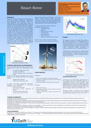
Develop a user-friendly and expandable system to monitor rotor current and frequency during testing. Utilizes LabWindows environment for software development and coordination with I/O boards.

E N D
BFG Rotor Run-In System David Johnson (EE) Dan Hansen (EE) Steve Feenstra (EE) John Postema (ME) Bryan Funke (ME)
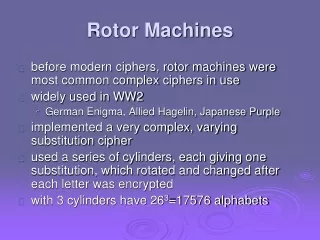
Problem Statement The rotor run-in system will allow for asynchronous testing of 16 rotors and will monitor and record rotor current and frequency. The system will be user friendly and easily expandable.
PC Components • PC with approx. 400 MHz processor and 128MB RAM. • Open PCI slots for at least three boards. • High speed digital input board (NI P/N: PCI-DIO-32HS) with 32 I/O lines • Digital I/O board (NI P/N: PCI-DIO-96) with 96 I/O lines • Analog I/O board (NI P/N: PCI-6033E) with 64 input lines • LabWindows environment used to develop software for communication with I/O boards and user interface.
Software • Coordinate and interface with I/O cards. • Interpret data. • Multiplex between groups of rotors. • Control LED’s for Pass/Fail and Power indication. • Log data to disk. • Allow for expandability for more fixtures. • Provide a user interface.
User Interface • Start test • Click Start button • Prompt for serial number • Settings menu • Select number of rotors • Select rotor velocity scale (RPM or Hz) • Display • Graphs of rotor speed • Pass/Fail indication • Abort test button
Scheduling • See Gantt Chart handout • Highly dependant upon availability of BFG resources. • Machining • Circuit Board Building
Deliverables • Working rotor run-in system • Software documentation • Mechanical Drawings • Electrical Drawings and Schematics • Troubleshooting Guidelines • Schematics for Upgrading