Download
1 / 40
400 likes | 432 Views
This paper discusses maintenance concepts for compact stellarators, focusing on the maintenance of blanket modules and disassembling of the coil system for blanket replacement. The challenges of forces acting on the coils and the design of the coil support structure are also addressed. The proposed solution involves enclosing the individual cryostats in a common external vacuum vessel.

E N D
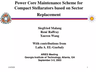
Power Core Maintenance Scheme for Compact Stellarators based on Sector Replacement Siegfried Malang René Raffray Xueren Wang With contributions from Laila A. EL-Guebaly ARIES Meeting Georgia Institute of Technology, Atlanta, GA September 3-5, 2003
Envisaged Maintenance Concepts for Compact Stellarators • Maintenance of blanket modules with an articulated boom, inserted through a small number of maintenance ports (ARIES meeting in January). • Disassembling of the modular coil system for blanket replacement (ASRA6C-Study, SPPS-Study). • Arrangement of maintenance ports between all modular coils (HSR-Study).
Three Kinds of Forces Acting on the Coils • Large centering forces pulling each coil toward the centre of the torus have to be reacted by a strong bucking cylinder. • Out-of plane forces acting between neighbouring coils inside a field period require strong inter-coil structure. • Weight of the cold coil system has to be transferred to the “warm” foundation without excessive large heat ingress.
Main Challenge for the Design of the Coil Support Structure • The movement of a field period as required for blanket replacement should be possible without disassembling coils, inter-coil structure and thermal insulation in order to avoid unacceptable long down time. • However, the transfer of large forces inside a field period and between coils and bucking cylinder is not possible between “cold” and “warm” elements. This means that the entire support structure has to be operated at cryogenic temperature. • To facilitate fast opening of the coil system, separate gyrostats for the bucking cylinder in the centre of the torus and for every field period are suggested.
Proposed Solution:Enclose the Individual Cryostats in a Common External Vacuum Vessel
Proposed Solution:Enclose the Individual Cryostats in a Common External Vacuum Vessel (Cont.)
Schematic of Arrangement of all Coils of a Field Period on a Supporting Tube
Arrangement of Long Legs to Support the Weight of the Cold Structure • Conflicting requirements: • Sufficiently large cross section of legs required to minimize mechanical stresses • Small ratio between cross section and length of the legs required to minimize heat ingress long legs
Arrangement of Long Legs to Support the Weight of the Cold Structure (Cont.) Example: • total weight of cold structure 1,800 tons • total number of legs 3x3 • required cross section of one leg: for example cylindrical tube with100mm diameter, 3 mm wall thickness • heat ingress between 300 K and 4 K with 0.5m long legs ~ 500 watt for all legs (Much longer legs shown in the sketch)
Arrangement of Legs Supporting the Weight of FW+Blanket+Shields Important difference compared to the legs supporting the cold structure: Much larger weight to be supported, but legs are between “warm” regions and therefore nearly no limitation on cross section. Example: 4 legs in each field period, 500 mm diameter, 35 mm wall thickness
Schematic Arrangement of Cooling Access Tubes to FW+Blanket+Shields Major features: • All access tubes are coming from the bottom. • Location of the access tubes close to points of mechanical support. • Concentric tubes with inlet flow in the annulus and outlet flow in the centre tubes allow for sliding seals in the centre tube.
Subdivision of FW, Breeding Blanket, and Shields • Minimize fabrication costs and mass of waste by separating regions requiring frequent replacement (“replacement units”) from the life-time components (“permanent zone”). • Choose an overall geometry allowing the removal of a replacement unit without disconnecting life-time components. • Split the required neutron shielding into high temperature and low temperature shield for two reasons: A. to enable passive low temperature cooling in the outer shield region for safety reasons, B. to minimize low temperature heat (“waste heat”) to <1% of total heat
Mechanical Support of the Different Components • Cold shield rests on warm legs, transferring the weight of the entire power core to the foundation. • Hot shield rests at the bottom only on the cold shield, allowing free differential thermal expansion. • FW+Breeding zone+support ring (“Replacement Unit”) slides on a rail located inside cold shield.
Steps to be Performed for an Exchange of Blankets The following major steps have to be performed for the replacement of blankets, either if they have failed or when they are at the end of their life time: • Warm up the coil system including the mechanical support structure. • Flood the plasma chamber and the cryostats with inert gas. • Cut all coolant connections to the field period to be moved, using in-bore tools operating from the bottom. • Open the outer side of the external VV in the range of the field period to be moved.
Steps to be Performed for an Exchange of Blankets(Cont.) • Slide the entire field period, composed of blankets, shields, cryostats, coils with inter coil structure, and all thermal insulation, outward in radial direction an the flat surface at the bottom. It should be possible to use an air-cushion system for this movement. • Cut the coolant access tubes to the blanket to be replaced. • Slide out from the openings at both ends the replacement units, composed of FW, breeding zone, and a structural ring (serving at the same time as a first high temperature shield). The replacement unit is movedoutwards in the toroidal direction on a rail attached to the replacement zone, and sliding on the low temperature shield. (Possibly with an air-cushion system, as discussed later)
Example of a Blanket Concept Suitable for Sector Maintenance • Every maintenance concept imposes particular requirements to the blanket design. If for example blanket modules are replaced with articulated booms through ports in the VV, the size of the modules and their weight are severely limited. This favours the use of self-cooled FliBe blankets with advanced ferritic steel as structural material, or self-cooled Pb-17Li blankets with SiC-composites as structural material. • Both concepts would be suited too for sector maintenance, but this maintenance scheme enables in addition the use of very large blanket units nearly without weight limitations. The idea is to minimize the coolant connections to be cut/rewelded for a blanket replacement, and to locate these connections close to the points of mechanical support in order to avoid problems with differential thermal expansion. • In order to increase the feasibility of the blanket concept, reduced activation ferritic martensitic steel has been selected as structural material. This does not rule out the use of other candidate materials such as advanced ferritic steels, vanadium alloys or even SiC-composites as structural material, but those materials are assessed in connection with other maintenance concepts.
Typical Parameters of the Blanket Replacement Units A first conceptual lay-out for the idealistic case of circular plasma with uniform cross section is based on the following assumption and parameters, and some issues in transferring this case to the real case of a CS (non-circular shape of the plasma, non-uniform cross section, non-planar coils) will be described later. - net electricity output of the plant 1000MW - gross electrical power 1100MW - efficiency of power conversion 47% Qthermal = 2340 MW ~ 2400MW - energy multiplication 1.2 Qfusion 2070MW - neutron power Qneutron 1656MW - average neutron wall load 2MW/m2 FW surface area 828m2 - major radius 8.5m - average minor radius 2.47m - 3 field period in CS - each field period subdivided into 2 blanket units - Qblanket = 400MW With these assumptions, the toroidal length of a blanket unit at the major radius is L = 2*pi*8.5m/6 = 8.9m and the average inner diameter of the unit isDi = 2* 2.47m ~ 5m
Possible Methods for the Movement of Blanket Replacement Units • The total weight of the “empty” replacement unit will be roughly 300,000kg if we assume that the unit is a closed ring, composed of a 0.6m thick breeding zone with a steel content of 8 % (including FW), followed by a ring of steel structure 0.1m thick (80% steel) to make any region outside this ring a life time component. • It is suggested to arrange a rail at the bottom of the replacement unit to slide this unit out of the permanent shield, moving it in the toroidal direction. Such a rail could be 8.9m long, and with an assumed width of 0.5m, the contact surface area would be roughly 5m2. The resulting contact pressure would be in the order of 0.6 MPa. Such a contact pressure is in the range of air cushion systems. An alternative solution could be to lift the replacement unit up and to install temporary rollers or low friction pads for easy movement.
Coolant Flow Scheme for Candidate Blanket Concepts The most simple blanket concept is a self-cooled liquid metal breeder blanket. There is no need for additional neutron multipliers as in solid breeder or FLiBe blankets, and there is no need for large internal heat transfer surfaces as in solid breeder blankets. Volumetric heating of the breeder/coolant provides the possibility to set thecoolant outlet temperatures beyond the maximum structural temperature and/or the maximum coolant/structure interface temperature limits. A preferred solution is to cool the FW and blanket with coolant flowing in the toroidal direction for two reasons: • If the FW coolant channels are made sufficiently large, the entire coolant flow of a blanket unit can be send first through the FW channels before it flows slowly through the breeding zone where it is heated up to a relatively high exit temperature. In this way, coolant manifolds (with flow in poloidal direction) and coolant access tubes are required at one end of the blanket unit only. • This is the main direction of the magnetic field. Depending on the strength of the field perpendicular to this direction, liquid metal coolant could be feasible without the need for electrically insulating coatings.
Lithium or the Eutectic Lead-Lithium Alloy Pb-17Li as Breeder Material? The two major liquid metal breeders - lithium and lead-lithium alloy have respective advantages and disadvantages. • Pb-17Li has slightly better breeding properties, and is less reactive with water or air, but the heat transport properties such as thermal conductivity and specific heat are much lower than those of lithium. • Lithium has a better compatibility with ferritic steel (allowable interface temperature up to 600 °C compared to < 500 °C for the alloy). Also, liquid metal cooling of the FW is perhaps possible with Li but is not feasible with Pb-17. • An alternative is to cool FW and the entire steel structure with helium, and to use Li or Pb-17Li as breeder/coolant in the breeding zone.
Possible Liquid Metal Blanket Concepts The overall flow scheme chosen in this study with the main flow in the toroidal direction provides the flexibility of using the following coolants schemes: • Self-cooled blanket with Li flowing in FW and breeding one. • Dual coolant blanket with helium cooled FW/structure and self-cooled Li-breeding zone. • Dual coolant blanket with helium cooled FW/structure and self-cooled Pb-17Li-breeding zone.
Thermal-hydraulic Design of the Selected Blanket Concept • The main parameters for one replacement unit (1/6 of entire machine): Total thermal power to be removed 400MW Heat to be removed with Li 300MW (75%of total heat, based on previous experience with dual coolant blankets) Heat to be removed with He 100MW Helium system pressure 8MPa Helium inlet/outlet temperature 400/500°C Lithium inlet/outlet temperature 500/800°C • Coolant access tubes to the replacement unit: Concentric tubes with an outer diameter of 0.8m as coolant access tubes to the module: - 1 for helium inlet/outlet, - 1 for lithium inlet/outlet. The coolant velocities in these tubes will be about 180m/s (helium) and 2.5m/s (lithium). Both values are acceptable.
Geometry of Cooling Channels and Manifolds A) Poloidal manifolds
Geometry of Cooling Channels and Manifolds (Cont.) B) Cross sections of toroidal cooling channels
Estimated Cooling Parameters • Helium cooling of FW velocity 70 m/s heat transfer coef. 4,200 W/m²-K inlet temperature 400 °C temperature rise 50 K pressure drop 0.1 MPa • Lithium cooling of breeding zone velocity 0.12 m/s inlet temperature 500 °C temperature rise 300 K heat transfer coef. 450 W/(m²-K) pressure drop 0.1 MPa (assuming B=1T perpendicular to flow direction)
Initial Results from Neutronics Analysis For a first lay-out of blanket and shields, the following questions had been addressed by Laila El-Guebaly with 1-D neutronics analyses: • What is the minimum thickness of the Li-zone (3% steel, 5% He, 92% Li) behind a 50 mm thick FW (30% steel, 70% He) to achieve T-self-sufficiency? • How thick a shielding zone (80% steel, 20 % helium) behind the breeding zone is required to make the region behind this shielding zone to a life-time component? • How thick an additional shielding zone is required to protect the coils, considering that that the winding pack is already enclosed by about 10 cm steel? The common assumption in all calculations was that 8% of the FW area is covered with shielding blankets only to account for the very limited space there. The Li-6 content in Li was varied from natural to 25 %. In addition, one analysis has been performed with Li replaced by Pb-17Li, enriched to 90% Li-6. The results indicates that the impact of the Li-6 concentration in Li and the differences between Li and the lead-lithium alloy on the required thickness of breeding zone and shields is rather small. Tritium self-sufficiency has been estimated with breeding zones between 47cm and 62cm thick. For sufficient shielding of the S/C coils, the steel shield has to be around 95 cm thick.
Conclusions from this Scooping Analysis • Uniform thickness of breeding zone and shields is far from an optimised geometry in a CS. There are regions where the space is severely limited, and there the breeding zone has to be eliminated or reduced to 10-20 cm. This can be compensated for with thicker breeding zones in most areas. • A shield composed of steel and helium only has very poor shielding properties. To achieve sufficient shielding in zones with limited space, either the steel has to be replaced by tungsten carbide and/or a neutron moderator has to be added. Unfortunately, the use of water as very effective moderator involves safety issues in case of accidents, if Li or to a lesser degree if Pb-17Li is used in the same containment. An alternative is to use Titanium-or Zirconium-Hydride in the low temperature shield. However, this will increase costs and has safety issues too which will be discussed.
Safety Issues Specific to the Proposed Maintenance and Blanket Concept • An important characteristic of the proposed maintenance concept for sector replacement is the arrangement of an external vacuum vessel. However, this arrangement has an implication on the following safety issues: a) It has to be assured that a potential spill of breeder or coolant does not cause damage to or high heat-up rate of the S/C coils. b) A reliable, passive cooling system for the low temperature shield is mandatory since the coil structure between LTS and VV does not allow the transport of after heat from the blanket to the environment by radiation. • Such an additional heat transport system based on natural convection in dedicated loops has been already designed in the ARIES-RS study as well as in the APEX EVOLVE study. Brad Merrill has investigated in the frame of EVOLVE a passive cooling system of the LTS and showed that the temperature in the LTS never exceeded a value of 700 °C. This is an important point if a hydride is used as moderator in the shield because a critical issue with these materials is decomposition of the hydride at temperatures > 700 °C. • The management of an in-vessel spill without damaging the coils seems feasible since there are large gaps between the field periods, enabling the spill to drain automatically to a catch pan arranged at the bottom of the VV. This has to be evaluated in a more detailed design.
Extrapolation of the Described Concept Principles and Solutions to a CS • For simplicity reasons all previous descriptions, figures and analyses are based on an idealistic case of a circular plasma with uniform cross section. • It has to be assessed if the suggested design principles can be applied for example to a NCSX-like plasma with large variations of plasma shape and size. • These variations are shown in the right figure . • Is it feasible with such a geometry to design a replacement unit(FW+Blanket) for extraction in toroidal direction?
Cross Sections at 60° Toroidal Angle • The plasma (red) is surrounded by the replacement unit (pink), composed of FW, breeding zone and a structural ring. • High temperature shield (blue) and low temperature shield (green) fit into the space between blanket and coil. • The question is, if the cross section of the replacement unit at 60° fits through the inside of the high temperature shield for example at 30°. • This check is made with the following figure.
Cross Sections at 30° Toroidal Angle • FW and blanket follow the plasma contour at this angle. However, there is in same regions a rather large distance between the outside of the replacement unit and the inside of the high temperature shield. • This space is required to allow a pull-through of the replacement unit cross sections from the angles 60, 50, and 40°. • The required cross sections at a toroidal angle of 0° are shown in the next figure.
Observations from the Motion Study of the Replacement Unit • It should be mentioned that the original distance of 1.2m between plasma and inside of the coils in the NCSX-like case would not allow such a movement. More space is needed at certain points which requires small changes either in plasma geometry, coil geometry, or thickness of blanket+shields. For drawing the figures A, B, and C, original sizes and shapes of plasma and coils are used but the thickness of blanket and shields has been reduced to 0.82m. • Figures A to C showed that there is sufficient space between coils and plasma to extract the replacement unit in toroidal direction. • However, such a movement is not possible on a circular rail centred at the torus-axis. • The replacement unit has to be moved to the outside on a different circular rail as explained in the following figure:
Rail-tracks for the Movement of Replacement Units • With the exceptions described, it can be concluded that the proposed maintenance method can be applied to plasma- and coil geometries similar to the one extrapolated from NCSX. • However, the extrapolation would be easier for geometries with smaller variation of the plasma cross section, and coils with smaller deviations from circular shape.
Summary, Conclusions (1) • A conceptual design of the toroidal field coil system for a Compact Stellarator including inter-coil structure, central bucking cylinder, cryostats, and external VV is proposed for sector maintenance. • The idea is to move an entire field period composed of blankets, shields, cryostats, coils with inter-coil structure, and all thermal insulation, outward in the radial direction after heating up the entire cold structure and opening the outer part of an external VV. • All coils and the inter-coil structure of a field period are enclosed by a common cryostat, and the out-of-plane forces of the coils inside a field period are reacted by a common structure maintained at uniform cryogenic temperature.
Summary, Conclusions (2) • After this movement, the two blanket replacement units in the field period can be removed on rails in the toroidal direction. A replacement unit is composed of FW, breeding zone and a structural ring serving at the same time as first neutron shield. • The high temperature shield outside this replacement unit as well as the surrounding low temperature shield are life-time components and do not have to be moved for a blanket replacement. • A blanket concept based on a self-cooled liquid metal breeding zone in a helium-cooled steel structure has been selected for this maintenance scheme. Typical thermal-hydraulic parameters are given for the case of lithium breeder, but it should be assessed whether the replacement of lithium by the eutectic lead-lithium alloy Pb-17Li would not be overall a better solution.
Summary, Conclusions (3) • First scoping neutronics analyses indicate that tritium self-sufficiency requires a rather large thickness of the breeding zone with such a concept, and the effectiveness of the neutron shield has to be increased by adding an hydride as neutron moderator or/and by replacing steel by the more efficient tungsten-carbide. • An initial assessment of the key safety issues indicate the feasibility of the proposed system on this basis. • All the descriptions, assessments and sketches are done for the simplified case of a circular plasma and planar coils. However, it is shown that the same principles can be applied to a NCSX-like system with non-circular plasma, varying plasma cross sections, and non-planar modular coils. • The results of this study can be used to compare different maintenance schemas and different blanket concepts with the goal of selecting a small number of combinations for more detailed evaluations.