Download
1 / 42
420 likes | 540 Views
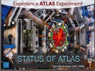
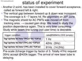
Status of the ATLAS experiment. Outline: Motivation for LHC and ATLAS History – time Status of the LHC machine Status af ATLAS and it’s subdetectors How we got here: - how to collaborate - comments on large scale and long lead time issues

E N D
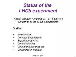
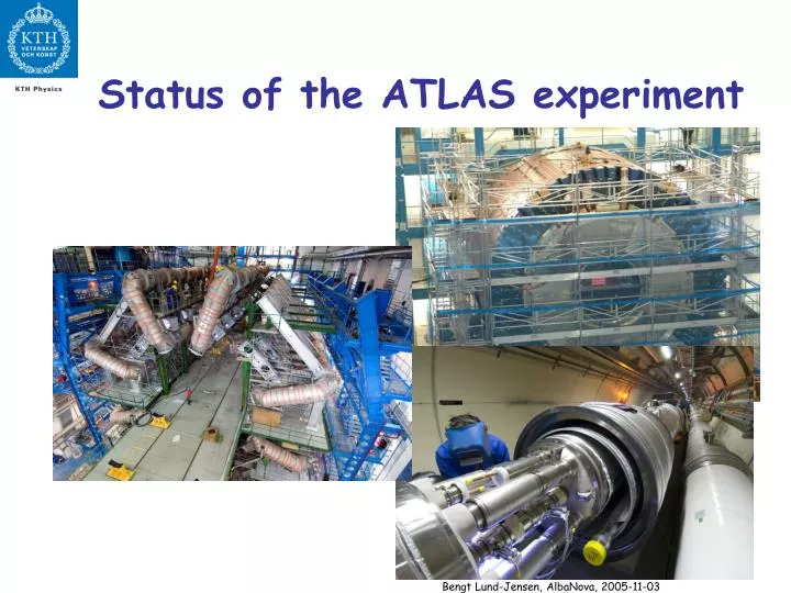
Status of the ATLAS experiment Bengt Lund-Jensen, AlbaNova, 2005-11-03
Outline: • Motivation for LHC and ATLAS • History – time • Status of the LHC machine • Status af ATLAS and it’s subdetectors • How we got here: • - how to collaborate • - comments on large scale and long lead time issues • - a selection of a few technical problems and solutions • positioning precision • Next steps: • - completion of installation • - commisioning Bengt Lund-Jensen, AlbaNova, 2005-11-03
Why a new accelerator? - The Standard Model of particle physics SU(3)CSU(2)LU(1)Y seems OK ! - Precision electroweak data support the SM and a light Higgs boson But: SM Higgs mass prediction • Are the masses really generated by the Higgs • mechanism? • So far the Higgs boson has not been found! • We need to find it or prove that it doesn’t exist! • High statistics measurements of top quark. • Does Supersymmetric (SUSY) particles exist? • Can SUSY explain the dark matter? • Large extra dimensions? • Other new physics? theLarge Hadron Collider ~10 times higher energy 10-100 times higher luminosity Bengt Lund-Jensen, AlbaNova, 2005-11-03
Value 26.7 km 8.4T 7.0 TeV 450 GeV 332 MJ 25 ns 2835 1011 540 mA 16 m 75 m 22 h 1034 cm-2s-1 10 h Parameters Circumference Dipole Field Collision energy Injection energy Stored beam energy Bunch spacing Number of bunches Particle per bunch Circulating current per beam Bunch radius Bunch length Beam lifetime Luminosity Luminosity lifetime A top quark factory Required for the discovery of the Higgs boson. NEW PHYSICS!! Excellent for CP violation studies with B-hadrons! Bengt Lund-Jensen, AlbaNova, 2005-11-03
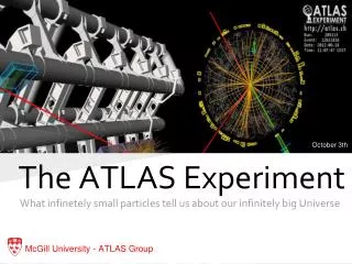
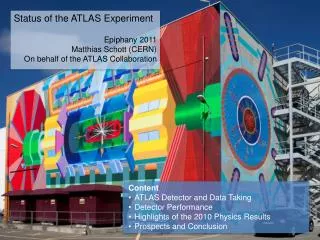
The ATLAS experiment Bengt Lund-Jensen, AlbaNova, 2005-11-03
ATLAS Collaboration 34 Countries and 152 Institutions 1770 Scientific Authors New since last OW: McGill Montreal (Canada) Massachusetts (US) Decision this Friday at the CB: Bologna (Italy) Osaka (Japan) New applications submitted: Dresden, Giessen (Germany) Oregon, Oklahoma (US) La Plata, Buenos Aires (Argentina) Albany, Alberta, NIKHEF Amsterdam, Ankara, LAPP Annecy, Argonne NL, Arizona, UT Arlington, Athens, NTU Athens, Baku, IFAE Barcelona, Belgrade, Bergen, Berkeley LBL and UC, Bern, Birmingham, Bonn, Boston, Brandeis, Bratislava/SAS Kosice, Brookhaven NL, Bucharest, Cambridge, Carleton, Casablanca/Rabat, CERN, Chinese Cluster, Chicago, Clermont-Ferrand, Columbia, NBI Copenhagen, Cosenza, INP Cracow, FPNT Cracow, Dortmund, JINR Dubna, Duke, Frascati, Freiburg, Geneva, Genoa, Glasgow, LPSC Grenoble, Technion Haifa, Hampton, Harvard, Heidelberg, Hiroshima, Hiroshima IT, Indiana, Innsbruck, Iowa SU, Irvine UC, Istanbul Bogazici, KEK, Kobe, Kyoto, Kyoto UE, Lancaster, Lecce, Lisbon LIP, Liverpool, Ljubljana, QMW London, RHBNC London, UC London, Lund, UA Madrid, Mainz, Manchester, Mannheim, CPPM Marseille, Massachusetts, MIT, Melbourne, Michigan, Michigan SU, Milano, Minsk NAS, Minsk NCPHEP, Montreal, FIAN Moscow, ITEP Moscow, MEPhI Moscow, MSU Moscow, Munich LMU, MPI Munich, Nagasaki IAS, Naples, Naruto UE, New Mexico, Nijmegen, BINP Novosibirsk, Ohio SU, Okayama, Oklahoma, LAL Orsay, Oslo, Oxford, Paris VI and VII, Pavia, Pennsylvania, Pisa, Pittsburgh, CAS Prague, CU Prague, TU Prague, IHEP Protvino, Ritsumeikan, UFRJ Rio de Janeiro, Rochester, Rome I, Rome II, Rome III, Rutherford Appleton Laboratory, DAPNIA Saclay, Santa Cruz UC, Sheffield, Shinshu, Siegen, Simon Fraser Burnaby, Southern Methodist Dallas, NPI Petersburg, Stockholm, KTH Stockholm, Stony Brook, Sydney, AS Taipei, Tbilisi, Tel Aviv, Thessaloniki, Tokyo ICEPP, Tokyo MU, Tokyo UAT, Toronto, TRIUMF, Tsukuba, Tufts, Udine, Uppsala, Urbana UI, Valencia, UBC Vancouver, Victoria, Washington, Weizmann Rehovot, Wisconsin, Wuppertal, Yale, Yerevan Bengt Lund-Jensen, AlbaNova, 2005-11-03
History of the development of LHC and ATLAS In the 1980’s various studies for a possible hadron collider in the LEP tunnel and ideas for detector technology. 1989 - ECFA Study week on instrumentation for high-luminosity hadron colliders, Barcelona. 1990 – LHC workshop in Aachen 7.7 on 7.7 TeV proton-proton collider (10 T). Physics cases studied. Instrumentation implications and ideas presented. 1990 - CERN instrumentation R&D programme initiated. About 50 RD projects where approved over time, covering detector elements, electronics and software. 1992 - 4 expressions of interest for LHC experiments where presented at Evian: ASCOT, CMS, EAGLE and L3 1992 - ASCOT and EAGLE merge to form the ATLAS collaboration. LoI. 1994 - LHC is approved by CERN council. 7 + 7 TeV, 8 T magnetic field 1994 – ATLAS Technical Proposal submitted. 1996 – ATLAS Technical Design reports 1997 – ATLAS construction approval. Cost estimate ~ 500 MCHF. 1997 - Preproduction started. Tendering started. 2004 - First subdetector installation in cavern March 2004. Support preinstalled. 2005 – (September) All barrel toroidal coils installed. Summer 2007 – first collisions ?? (In 1990 the planned start date was in 1997-1998 before SSC.) Bengt Lund-Jensen, AlbaNova, 2005-11-03
Status of the LHC machine Bengt Lund-Jensen, AlbaNova, 2005-11-03
Superconducting cable 1 Bengt Lund-Jensen, AlbaNova, 2005-11-03
The magnet production proceeds very well and is on schedule, also the quality of the magnets is very good Dipoles ready for installation Bengt Lund-Jensen, AlbaNova, 2005-11-03
Cryogenic distribution line Repair of the cryogenic service lines (QRL) Cryogenics (QRL) in the tunnel On the critical path for the first collisions in Summer 2007 is the installation of the LHC in the tunnel, in particular due to delays in the cryogenic services lines (QRL) which in 2004 had problems, and for which a recovery plan was implemented successfully. (The problem was due to the welding quality of pipes.) Bengt Lund-Jensen, AlbaNova, 2005-11-03
Magnet Installation Interconnection of the dipoles and connection to the cryoline are the real challenges now in the installation process Transport of dipoles in the tunnel with an optical guided vehicle Bengt Lund-Jensen, AlbaNova, 2005-11-03
First injection in TI8 on 23 October 2004 Bengt Lund-Jensen, AlbaNova, 2005-11-03
Status of ATLAS Bengt Lund-Jensen, AlbaNova, 2005-11-03
Cavern Jan 2004 Bengt Lund-Jensen, AlbaNova, 2005-11-03
Cavern Today Bengt Lund-Jensen, AlbaNova, 2005-11-03
The last Barrel Toroid coil was moved into position on 25th August and the structure was released from the external supports on 29th September Bengt Lund-Jensen, AlbaNova, 2005-11-03
The ATLAS experiment Bengt Lund-Jensen, AlbaNova, 2005-11-03
Cosmics recorded in the barrel TRT Integrated end-cap TRT wheels of the initial detector for one side Bengt Lund-Jensen, AlbaNova, 2005-11-03
A cosmics muon registered in the barrel Tile calorimeter The barrel LAr and Tile calorimeters are ready since some time in the cavern in their ‘garage Position’ to be moved into their final position today Bengt Lund-Jensen, AlbaNova, 2005-11-03
Muon system installation Bengt Lund-Jensen, AlbaNova, 2005-11-03
How did we get here? Bengt Lund-Jensen, AlbaNova, 2005-11-03
Organization: ATLAS has been organized in a tree structure with subgroups, each with a (sub)project leader. Indivudual institutions join subgroups according to their interest. Management: Project Leader + deputy, Techn. Coord, Resource Coord Executive Board Inner Detector Liquid Argon Calorimeters Tile Calorimeter Muon System Magnets Trigger & DAQ Computing … Pixel Silicon Tracker Transition Radiation Tracker Bengt Lund-Jensen, AlbaNova, 2005-11-03
Decision making: Decisions in ATLAS are taken by Collaboration Board (or Group Representative Boards) where each institute has one vote. The proposal for the decision is prepared in/by subgroups and management at the level where the decision is taken. All major decisions, like technology for a specific subdetector, where voted for or approved by the ATLAS collaboration board. Examples: Accordion geometry was selected compared to thin gap geometry for the liquid argon calorimeter in 1992. Place was found for the groups working on the thin gap geometry to join the liquid argon hadronic endcap technology. Bengt Lund-Jensen, AlbaNova, 2005-11-03
Technological challenges and problems along the way. • Long lead time technology frozen early. Use state of the art at the time. • In some cases choices were changed due to technological development. • Technology may be outdated at start of LHC. Impossible to get spare parts. • E.g. trigger boards purchased 10 % spares at each level, i.e. for each module type 10% spares, for each board in the module 10 % spares, for each component 10 % spares. • Example: Early development of some radiation hard electronics required DMILL technology. Newer silicon technology with sufficiently rad-hardness. • DMILL outdated. • Large scale production in industry. • Tendering. Not always possible to get a company involved in the development to be the producer. Selected company may have miscalculated effort and quality required. • (Of course important to obtain the lowest cost for the reuqired quality). • Quality control. • Companies do not fulfil requirements according to the order. • Bankruptcy of company during production. Bengt Lund-Jensen, AlbaNova, 2005-11-03
Example: The presampler printed circuit board anode electrodes. Requirements within the standard (NEMA) for all printed circuit boards. 1st tendering: Scottish company selected. Failed to produce any board. Sales organization had not checked intyerest of prodcution unit. 2nd tendering: Italian company selected. OK during small test production. In large scale production (22000 boards) about 10 % failed high voltage insulation criteria. Some boards showed failures after several days. All 22000 boards returned to producer. 3rd tendering: A small company in Belgium that produced some boards during prototyping selected. Production successful. Bengt Lund-Jensen, AlbaNova, 2005-11-03
Examples of a few problems seen along the way and solutions: Some ”dust” inside the liquid argon cryostats penetrate into the active gaps of the presampler and the calorimeter. The principle of operation is to collect ionization charges from the se gaps applying 2 kV across. Dust short circuit, gap dead. Solution: discharge capacitor across the short circuit. Complication: the high voltage feed lines have constantan connection wires to reduce heat losses inside the cryostat. This introduces some tens of Ohm resistance. The presampler also has a 1 MΩ decoupling resistor in series. With sufficient voltage across the surface mounted resistor a spark bypassing it is formed!! If the short circuit is solid, the thin lead on the board may act as a fuse. Tested with 50 μF, 2kV and 30 Ω constantan wire. It works!! In most cases, however, the short circuit disintegrates more easily than the copper lead on the board!! The same solution has been used to burn a short circuit inside one of the calorimeter gaps (though no thin line that may serve as a fuse). Bengt Lund-Jensen, AlbaNova, 2005-11-03
Pixel cooling pipes • A problem appeared at end-July: • Corrosion of stave cooling pipes • Caused by nickelization of the pipe endings (needed to braze the fittings) and exposure to water without proper drying procedure galvanic corrosion 15% of pipes leaky. Note: freon is used for the cooling • All experts consulted agreed on the need to change all the pipes (hard to stop corrosion). • Now, laser welding has been approved and will be used instead of fittings Bengt Lund-Jensen, AlbaNova, 2005-11-03
Example of challenge:Barrel Transport Bengt Lund-Jensen, AlbaNova, 2005-11-03
Barrel Transport * This condition on the time imposed to distinguish a sinusoidal excitation (engine) from the shock caused by a road imperfection Bengt Lund-Jensen, AlbaNova, 2005-11-03
courtesy J.Bonis, LAL DYNAMIC BEHAVIOUR -1- Model: 3D, 8 absorbers, connected together by a rigid body Material: simulate an elastic behaviour similar to the sandwich steel/polymer/lead Sinusoidal excitation of 0.1g along Y, between 10 and 110Hz, damping factor per mode 1% (high damping: friction + material properties) Excitation of one dangerous mode at 20Hz (coupled vibration of the zero-order harmonics of one individual absorber) Bengt Lund-Jensen, AlbaNova, 2005-11-03
courtesy J.Bonis, LAL DYNAMIC BEHAVIOUR -2- The danger related to this oscillation: detachment of metal impurities which may cause short-circuits between absorber and honeycomb (REMEMBER the absorbers are cleaned by vibration) Bengt Lund-Jensen, AlbaNova, 2005-11-03
M k VIBRATIONAL DAMPING Road transport: active damping with an elastomer plate inserted between charge and trailer additional damping expected from hydr.jacks piloting the platforms Lowering in the cavern active damping by the oscillating system constituted by the suspended charge low speed to diminish the effect on vertical acceleration due to emergency stop Bengt Lund-Jensen, AlbaNova, 2005-11-03
Barrel calorimeters 27 October 2004 -> 14 January 2005 A-Frames = final LAr supports Alignment Tooling (during insertion) Completion of Tile Cal Bengt Lund-Jensen, AlbaNova, 2005-11-03
Measured acceleration during transport: • Except for one incident (lorry had to break): • z (longitidinal) < 3*10-2 g • x < 10-3 g • y < 10-2 g • Maximal longitudinal slope: 1.5 % • Maximal transverse slope: 2% (5 corrections during the transport) • Incident: • (z):0,1g • (y):0,005g • (x):0,02g Bengt Lund-Jensen, AlbaNova, 2005-11-03
And the end-caps are coming soon… here the LAr end-cap C on its way (22nd September) Bengt Lund-Jensen, AlbaNova, 2005-11-03
Positioning precision: The position of the 175 ton liquid argon calorimeter inside the tile calorimeter has been adjusted to within 1-2 mm. Excellent in view of the deformation caused by 175 tons!! • Cavern floor: • The cavern has been excavated removing rock. The floor now rises with an assumed movement of ~ 0.8 mm /year. • Adjust ATLAS to be a few mm below the beam line such that the optimal position is obtained around 2010 when LHC has achieved optimal tuning. Shims to adjust position Legs attached to Tilecal support Bengt Lund-Jensen, AlbaNova, 2005-11-03
Next steps: • Completing installation • Commisioning Bengt Lund-Jensen, AlbaNova, 2005-11-03
Barrel Toroid installed • Cable ladders may be installed and cabling started. (Some cabling already prepared by installing from electronics cavern to the structure just outside the toroid coils). Inner detector and endcaps remain. Tight schedule. Detailed day by day program exists. Some unexpected problems can be accomodated. Considerations: • number of persons underground at the same time is limited. • access to different detector parts depends on other installation tasks • access during magnet tests restricted. Bengt Lund-Jensen, AlbaNova, 2005-11-03
Example: 2005 Tile barrel schedule commissioning V 7.08 (present best understanding of schedule with barrel at z=0 on 26 Oct.) • 27 Oct ’05 – 8 Feb ‘06: barrel commissioning rotating in sectors (2 sect=16fingers): • 9 Feb – 9 Mar ‘06: Calibration (CIS, laser, cesium, cosmics) for 2 full partitions with ROD’s + DAQ + DCS + LTP + … • Spring ‘06: integrate with LAr Bengt Lund-Jensen, AlbaNova, 2005-11-03
Conclusions One of the largest and most complex expertimental set of equipment is nearing its succesful completion. Being ready for first collisions summer 2007 seems feasible. A great time of exploration of fascinating physics is ahead!! Bengt Lund-Jensen, AlbaNova, 2005-11-03