Download
1 / 4
0 likes | 9 Views
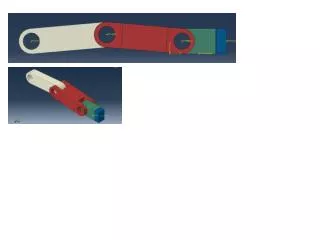
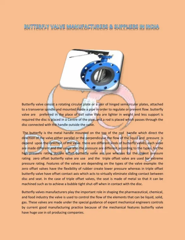
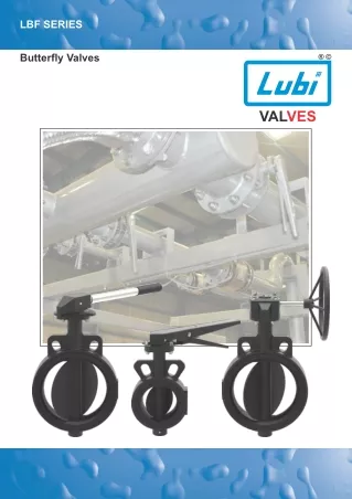
We have designed & manufacture the Lubi Valves LBF series type of Butterfly Valves for General Utility Water applications as well as for HVAC applications.

E N D
LBF SERIES Butterfly Valves VALVES
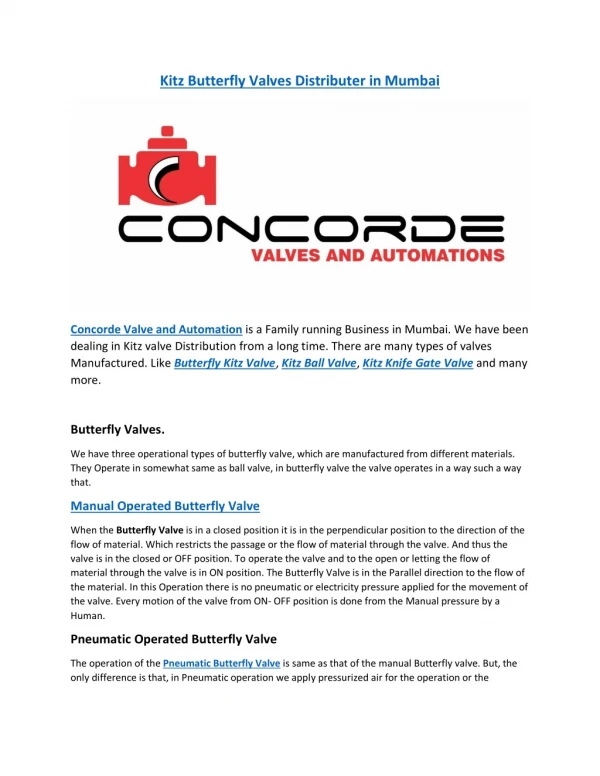
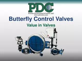
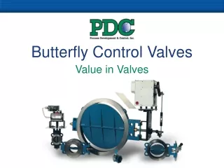
LBF BUTTERFLY VALVES INTRODUCTION • We have designed & manufacture the Lubi LBF series type of Butterfly Valves for General Utility Water applications as well as for HVAC applications. • It is a type of quarter turn valve which means that it can be fully opened or closed when the disc is rotated a quarter turn. MAIN FEATURES • Butterfly Valves are easy to open & close. • They are easy to install due to their compact design & less space requirements at the place of installation. • We provide Tight Sealing due to close interference between disc & liner. We also provide a Triple Stem Seal which prevents any leakage and also any foreign particles from entering the valve. • The flow control lever as well as the gear unit are designed such that very low torque is required for controlling the valve. Also, the hand lever can be held in several positions whereby the disc position in valve is not affected by the flow pressure. • These valves have very low pressure drop. • We provide all our valves with CED coating which gives better corrosion resistance & hence gives long lasting life. Maximum Working Temperature: 110°C (230°F) APPLICATIONS Stem Top stem 'O' ring seal The main applications of this valve is for general utility water applications as well as HVAC applications. The typical applications areas are as follow: On/off isolation Dead-end service/removal of down stream piping Industrial process water piping Municipal raw water intake Municipal chlorinated water systems Full vacuum Aeration and blower applications. Bottom stem 'O' ring seal Flat surface seal TRIPLE STEM SEALING LBF P10 W 50 C D E 0 L Lubi Butterfly Valve Pressure rating P10 - PN10 P16 - PN16 Body style Body liner E = EPDM N = Nitrile V = Viton Body material C = Cast Iron D = Ductile Iron Stem 0 = SS410 4 = SS304 W = Wafer type Handle Disc material D = Ductile Iron 4 = SS304 6 = SS316 40 = 40 mm 50 = 50 mm 65 = 65 mm 80 = 80 mm 100 = 100 mm 125 = 125 mm 150 = 150 mm 200 = 200 mm 250 = 250 mm 300 = 300 mm L = Lever G = Gear Operator
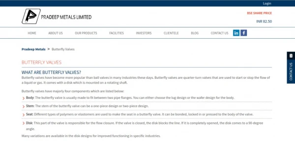
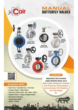
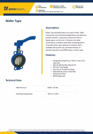
LBF BUTTERFLY VALVES DESIGN FEATURES Actuator mounting flange Shaft/Stem ‘O’ ring Liner Valve body Disc ‘O’ ring MATERIAL OF CONSTRUCTION Part Name Material Valve Body Liner *Disc Shaft/Stem * DN 40 available only in Ductile Iron & Al Bronze. Cast Iron, Ductile Iron EPDM, Nitrile , Viton Ductile Iron, CF8, CF8M, AI Bronze Carbon Steel (EN8), Stainless Steel AISI 410, Stainless Steel AISI 304
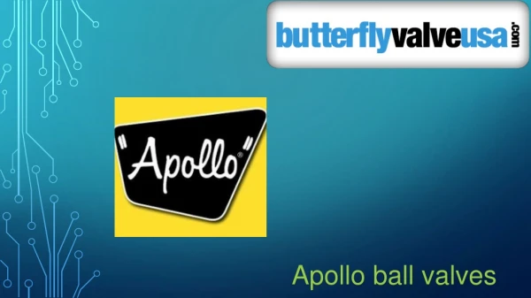
LBF BUTTERFLY VALVES TECHNICAL DATA L L B B H H C C C d d d A A A D T t T t T t VALVE SIZE: DN 40 TO DN 150, DN 300 VALVE SIZE: DN 200 TO DN 250 VALVE SIZE: DN 40 TO DN 300 VALVE WITH GEAR UNIT VALVE WITH FLOW CONTROL LEVER Dimensions [mm] Valve Size Flange Mounting (ISO 5211) Torque* [Nm] Flow Control Lever mm inch T C A D d t B L H 4 10 10 24 28 30 44 102 156 178 DN40 DN 50 DN 65 DN 80 DN 100 DN 125 DN 150 DN 200 DN 250 DN 300 1½ 2 2½ 3 4 5 6 8 10 12 36 44 60 74 96 120 144 198 248 300 35 45 48 48 54 58 58 61 74 85 103 113 118 127 150 165 185 235 260 285 55 65 70 79 96 107 125 150 185 204 78 95 105 123 157 179 211 261 322 369 3 3 9 268 268 268 268 268 268 268 397 515 508 300 300 300 300 300 300 300 463 608 610 134 138 147 156 179 194 215 290 325 345 F05 F05 F05 F05 F05 16 24 34 46 70 90 111 F05 / F07 F05 / F07 F07 F10 F10 Note: * A safety factor of 25% should be added to these figures, while sizing for an actuator. STANDARDS PRESSURE TESTS PN10 PN16 Design Actuator mounting flange Testing Hydrostatic Shell Test Seat Test Maximum Working Pressure EN 593 / ISO 5752 ISO 5211 ISO5208 / API598 / EN 12266 15 bar (218 psi) 11 bar (160 psi) 10 bar (145 psi) 24 bar (350 psi) 17.6 bar (256 psi) 16 bar (230 psi) LUBI INDUSTRIES LLP Near Kalyan Mills, Naroda Road, Ahmedabad-380 025, INDIA. Phone : +91 - 79 - 61700100, Fax No. :+91 - 79 - 61700399. Sales Enquiries: sales@lubivalves.com www.lubivalves.com Product Improvement is a continuous process at ‘LUBI’. The data given in this publication is therefore subject to revision. 02.02.230223.0124 Customer Care Number : 09824200800