Potentiostat
Team Members: Kyle Bloomer Josh Geiman Lucas Bennett. Potentiostat. What is a Potentiostat?. A Potentiostat is the electronic hardware required to control a three electrode cell and run most electro-analytical experiments .


Potentiostat
E N D
Presentation Transcript
Team Members: Kyle Bloomer Josh Geiman Lucas Bennett Potentiostat
What is a Potentiostat? • A Potentiostat is the electronic hardware required to control a three electrode cell and run most electro-analytical experiments. • An electronic instrument that controls the voltage difference between a Working Electrode and a Reference Electrode. • It measures the current flow between the Working and Counter Electrodes.
Past Potentiostat Projects • Two past projects completed by a prior capstone group, and Ben Williams, a Masters student, both based on the “ardustat” project • Current design utilizes only two electrodes • Noise issue with closing a dry contact relay, especially when taking measurements moments after closure. • No circuit protection • Current design has a graphical user interface that has functionalities that are largely inoperable, and needs a ‘ground up’ revision
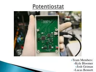
Cheapstat • Developed by UCSB as an affordable alternative to OTS potentiostat devices • Three electrode configuration • Numerous measurement modes • Input parameters set through onboard LCD and 5-way joystick • Our team plans to streamline the design, removing these parts and passing configuration utility to the Data/Display Management System.
Background Info • Dr. Cindy Harnett's laboratory is in need of up to 15 potentiostats for testing a variety of electrochemical devices. • Off the shelf potentiostats range in price from 5-10k+, which necessitates an affordable alternative that can be both built and assembled by students.
Project Requirements • Must cost under $100 • Must have the ability to measure Electrochemical potential • Must be easy for undergrad and graduate students to assemble and use • Must be well documented for future projects and maintenance
Function of System • Function of system as an entity • Measures characteristics of electrolytic cells • Results of measurements reported from processor to Data/Display Management System through USB connection • Communicate results of test to user via Data/Display Management System
Data/Display Management System Requirements • The Data/Display Management System manages three sub components • System control • Software on the PC will provide the user with means to specify the appropriate parameters • Data logging • The PC will have the ability to keep records of the measurements returned from the Potentiostat • Data display • After testing is successfully finished, the user will have the ability to view results on the PC
Voltage Converter • “Wall Wart” • 120VAC, 60Hz, 15A input power • 5VDC, up to .5A output power • 5VDC to 3.3VDC will be done on the PCB • If power consumption can be limited to 125mA input, Device can be powered via USB, eliminating this system component
Operational Concept • The PC is connected to the potentiostat • Software with a Graphical User Interface program will run on a PC • The user will have the ability to change configuration of the test device through the GUI program to send to the potentiostat • Once the potentiostat is finished executing the test, the user will then receive the results through the software and have the ability to review them on the GUI.
External Interfaces • PC with USB connection • For the Potentiostat to communicate with the PC, a connection must be established through a USB interface • DC Power Converter • A DC power converter must be utilized within the system to allow 120VAC, 60Hz, and 15A of operational power
Internal Interface • USB Connection • Windows Operating System • Software to Software Interface
Intelligent Potentiostat Requirements • The Potentiostat manages two functions • Data communication • The function of this subcomponent is to communicate all data from the PC Interfacing Control to the Potentiostat system • Device Under Test (DUT) measurement
Data/Display Management System Software • Data/Display Management System • The Data/Display Management System will handle 4 main requirements through C# Program • Simplistic GUI for Data Controlling • Transmit the configuration to the controller • Initiates measurement process • Retrieves raw data
System Description • The PC Software will allow user to configure the test profile • The user will have the ability to select various waveforms and also set the maximum voltage applied by the potentiostat • The results of each measurement will then be reported back to the user
Current Status • CheapStat Parts to be ordered today • Designing the GUI portion of the PC Software to best fit requirements • Testing preexisting Cheapstat