Download

1 / 53
1.07k likes | 3.18k Views
Working length determination. The determination of an accurate working length is one of the most critical steps of endodontic therapy. The cleaning, shaping and obturation of the root canal system cannot be accomplished accurately unless the working length is determined precisely.

E N D
The determination of an accurate working length is one of the most critical steps of endodontic therapy. • The cleaning, shaping and obturation of the root canal system cannot be accomplished accurately unless the working length is determined precisely
THE SIGNIFICANCES OF WORKING LENGTH ARE. • The working length determines where the instruments are placed in canal and removal debris, metabolities, end products, & other unwanted items form the canal. • It will limit the depth to which the canal filling is placed. • It will affect the degree of pain and discomfort that the patient will feel following the appointment. • If calculated properly, it will play an important role in success of the treatment and if calculated incorrectly result in treatment failure.
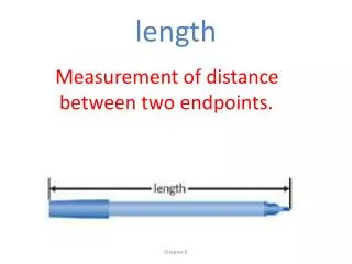
ANATOMICAL CONSIDERATIONS AND TERMINOLOGY Simon has stressed the use of terms related to working length determination. • WORKING LENGTH: - - “The distance from a coronal reference point to the point at which canal preparation and obturation should terminate”. The ideal apical reference point in the canal is “apical stop”. • ANATOMIC APEX: - Is the tip (or) the end of the root determined morphologically. • RADIOGRAPHIC APEX: -Is the tip (or) the end of root determined radiographically.
APICAL FORAMEN: • Is the region where the canal leaves the root surface next to the periodontal ligament, it is the main apical opening of the root canal. • It is frequently eccentrically located away from the anatomic (or) radiographic apex. Kuttler’s investigation showed 68 to 80% of teeth are deviated. • The anatomy of apical foramen changes with age. (a) The concept of the apex (b) The apex of a younger person (c) changing apex due to hard tissue deposition.
ACCESSORY FORAMEN: - Is an orifice on the surface of the root communicating with a lateral (or) accessory canal. They may exist as a single foramen (or) as multiple foramina. • APICAL CONSTRICTION: - (Minor diameter) is the apical portion of the root canal having the narrowest diameter. The minor diameter widens apically to the foramen (major diameter) and assumes a funnel shape. The difference in length between the major and minor diameter will increase with age. • “The morning glory flower configuration” is clearly visualized in an obturated radiograph when sealer is slightly extrudes past the apical constriction.
Dummer et, al (1984) classified the apical constriction into four distinct types.
THE CEMENTODENTINAL JUNCTION (CDJ):- Is the region where the dentin and cementum are united, the point at which the cemental surface terminates at (or) near the apex of a tooth • ENDOMETRY: The term endometry refers to the accurate determination of the working length, which decides the apical termination part for all inter canal procedures from a reference point.
Reference point • In anteriors: incisal edge • In posteriors: cusp tip
METHODS OF DETERMINING WORKING LENGTH • THE MOST COMMON METHODS ARE. • RADIOGRAPHIC METHODS. • ELECTRONIC METHODS. • AUDIOMETRIC METHOD. • DIGITAL TACTILE SENSE METHOD. • PAPER POINT MEASUREMENT. • PATIENT RESPONSE.
RADIOGRAPHIC METHODS ARE GROSSMAN‘s method. INGLE‘s technique. WEINE’s modification. CURVED canals. OTHER METHODS, • BEST METHOD. BREGMEN METHOD. BRAMANTE METHOD. EVERETT AND FIXOT GRID SYSTEM. EUCLIDEAN ENDOMETRY. RECENT ADVANCES IN RADIOGRAPHIC METHODS, RADIOVISIO GRAPHY. (RVG) XERORADIO GRAPHY. DIGITAL IMAGE PROCESSING. LASER OPTICAL DISK STORAGE.
GROSSMAN’s METHOD. • According to Grossman, an instrument extending to the apical constriction is placed in the root canal is determined by digital tactile sense and a radiograph is taken. • A mark (or) stopper is placed at the occlusal (or) incisal reference point which will also be detectable on the radiograph. • By measuring the length of radiographic images of both the tooth and measuring instrument as well as the actual length of the instrument the clinician can determine the actual length of the tooth by a mathematical formula. • The disadvantage of this method is that a small error will be multiplied.
1) Grossman’s Method: Actual length X Radiographic Actual WL =Of the inst Length of tooth Radiographic length of inst
INGLE’ TECHNIQUE:- The following items are essential to perform this procedure. • Good, undistorted, preoperative radiographs showing the total length and all roots of the involved tooth • Adequate coronal access to all canals. • An endodontic millimeter ruler. • Working knowledge of the average length of all of the teeth.
WEINE’s modification: • Weine’srecommendations for determining working length based on radiographic evidence of root / bone resorption. • If no root (or) bone resorption is evident preparation should terminate 1.0mm from the apical foramen. • If bone resorption is apparent but there is no root resorption shorten the length by 1.5mm • If both root and bone resorption is apparent shorten the length by 2.0mm.
BEST METHOD • In this method, as described by Best: A 10mm steel pin was fixed to the labial surface of the tooth with utility wax in a position parallel to its long axis before radiograph obtained. The radiograph so obtained was carried to the BW gauge which indicates the tooth length. • Best attained little success, generally resulting in lengths greater than the real length of the teeth.
BREGMAN METHOD • In this method flat probes, 25mm. in length, were prepared. Each had a steel blade fixed with acrylic resin as a stop, leaving a free segment of 10mm for placement into the root canal. This probe was placed in the tooth until the metallic end touched the incisal edge (or) cusp tip of the tooth. Then a radiograph was taken.
In the radiographic image the following factors were measured: CAD = Apparent tooth length, seen in the radiograph. CRI = Real instrument length. CAI = Apparent instrument length, seen in the radiograph. • To these factors the following formula was applied: The real tooth length is CRD CRI X CAD CRD = CAI
BRAMANTE METHOD • Bramante, in 1970, presented a method to determine the tooth length, employing stainless steel probes of various calibers and lengths. • These were bent at one end, forming a right angle, and this bend was inserted partially in acrylic resin, in such manner that its internal face was flush with the resin surface contacting the tooth surface. • The probe was introduced into the root canal so that the resin touched the incisal edge or cusp tip, taking care to see that the bent segment of the probe would be parallel to the mesiodistal diameter of the tooth crown, thus making it possible to visualize it on the radiograph. • Then the tooth was radiographed.
The tooth length was calculated in two different ways. • Measuring the radiographic image length of the probe A to B; measuring the radiographic image length of the tooth from A to C; measuring the real length of the probe. To these data, the following equation may be applied: • This method is a variation that follows the principles of the Bregmen method. CRS x CAD CRD = CAS CRD = Real tooth length CRS = Real probe length CAD = Tooth length in the radiograph
Measuring the distance between the apical end of the probe (B) and the tooth apex (C) in the radiograph, adding or diminishing this measurement of the real length of the probe, in this way obtaining the tooth length. • This method is a variation that follows the principles of the Ingle method.
GRID SYSTEM: • Everett and Fixot (1963) designed an x-ray grid system for determining the length of the tooth. • The diagnostic x-ray designed consists of lines 1mm a part running length wise and cross wise, every fifth mm is accentuated by a heavier line to make reading easier on the radiograph • The grid is taped to the film to lie between the tooth and film during exposure so that the pattern becomes incorporated in the finished film. • The tooth length determined by this method is more accurate than by other methods.
EUCLIDEAN ENDOMETRY: • An extra canal length determination method called Euclidean endometry was developed. • This uses two geometrically distorted radiographs in determining the real length of the tooth. • The two radiographs are taken with a cone fitted with an “Updegraves XCP” (Extension cone paralleling method) device at two different vertical angulations
Disadvantages of radiographic methods • Anatomic structures and radiopaque materials may be super imposed on the image of the root. • The biologic risk of radiation. • The procedure is time consuming. • Radiograph is a two dimensional representation of a three dimensional object. • The apical foramen could not be correctly identified because it frequently deviated from the anatomic apex. • Patient with gag reflex (or) limited mouth opening may inhibit taking radiographs.
RECENT ADVANCES IN RADIOGRAPHIC METHODS, • RADIO VISIO GRAPHY. (RVG) • XERORADIO GRAPHY. • DIGITAL IMAGE PROCESSING • LASER OPTICAL DISK STORAGE.
Xero-radiography – edge enhancement Xero-radiography uses a uniformly charged selenium alloy photo receptor plate held in a light proof cassette.
Advantage: Quick development (30 sec.) Does not require wet chemical processing or dark room. Good edge contrast so tissue appears sharper. 1/3rd the usual exposure time .
RVG system was developed by Dr. Francis Mouyen. • It has three components: • The radio component consists of a high resolution sensor The ‘RADIO’ part consists of a conventional x-ray generator connected to a highly precise microprocessor timer for very short exposure times and an anatomically adopted sensor with rounded edges and angles. • The sensor has a sensitive area of 17 X 26mm2 consisting of an exchangeable scintillation screen, a fiber optic, and a miniature charged coupled device imaging system. • The Visio portion consists of a video monitor and display processing unit
Third component is the ‘Graphy.’ a high-resolution video printer that instantly provides a hard copy of the screen image
Advantages: • Radiographic images are obtained immediately • Developing time and film processing is eliminated • Radiation exposure is reduced from 50% to 90% compared to conventional film-based radiography. Disadvantages: • High cost • Reduction in image quality when compared to conventional X-ray
Electronic method:Apex locator works on this method • BASIC FUNCTIONS OF EAL’S • All apex locator’s function by using the human body to complete an electrical circuit one side of the apex locator’s circuitry is connected to an endodontic instrument. • The other side is connected to the patient’s body; either by a contact to the patient’s lip (or) by an electrode in the patients hand. • The electrical circuit is complete when the endodontic instrument is advanced apically inside the root canal touches the PDL.the display on the apex locator indicates that the apical area has been reached. • WL is determined by comparing electrical resistance of periodontal membrane with that of the gingiva surrounding the tooth and both should be similar • .
Invented by Sunada in 1947. It is an electronic device, to which an endodontic inst is attached and placed in a dry canal and slowly advanced till it contacts the periodontal ligament (apex) and at that point electrical resistance for both gingiva and P. Ligament shows similar reading
CLASSIFICATIONS OF ELECTRONIC APEX LOCATORS • 1st Generation apex locators • Also known as RESISTANCE apex locators. • Eg: Neosono,Dentometer • Principles: measures opposition to the flow of direct current (or) resistance. • . • .
2nd second generation apex locators • Also known as IMPEDANCE apex locators. Eg: ENDO ANALYZER , FORMATRON • Principle: Measures opposition to the flow of alternating current (or) impedance
The 3rd generation apex locators • Are similar to 2nd generation except that they use multiple frequencies to determine the distance from the end of the canal. • ENDEX: (or) APIT , ROOT ZX • In biologic settings, the reactive component facilitates the flow of alternating current, more for higher than for lower frequencies. Thus a tissue through which two alternating currents of different frequencies are flowing will impede the lower frequency current more than the higher – frequency current.
Fourth generation • A device and the unit use two separate frequencies 400 HZ and 8 KHZ similar to the 3rd generation units • The BINGO 1020 / RAY – PEX 4. • The manufacturers claim that the combination of using only one frequency at a time and basing measurements on the root mean square values of the signals increases the measurement accuracy and the reliability of the device.
COMBINATION OF APEX LOCATOR & ENDONTIC HANDPIECE • The Tri Auto ZX is primarily a cordless automatic, endodontic handpiece with a built in Root ZX apex locator
ADVANTAGESOF THE ELECTRONIC METHOD Only method that can measure length up to apical foramen, not to radiographic apex.. Accurate Easy and fast Reduction of X-ray exposures Artificial perforation can be recognized DISADVANTAGESOF THE ELECTRONIC METHOD. Requires special device Accuracy is influenced by electrical condition of canal Difficult in teeth with wide open apex. Inconsistent results in cases of vital teeth (except newly developed devices). False when canal is wet ,in contact with metal ,in perforations,pulp in not completely removed
Audiometric method • Eg: Sonoexplorer • Is a variation of electronic method, uses low frequency oscillation sound to indicate the apical foramen. • Invented by Inoue in 1985. • In this method first the instrument is placed in the gingival sulcus and current is induced till the sound is produced, and then repeated by placing it in the root canal until the same sound is heard and thus W.L is measured.