Download
1 / 10
100 likes | 186 Views
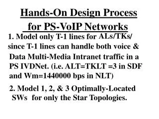
Hands-On Design Process. for Integrated V/D Networks. 1. Model only 56 KBPS lines since 56000. BPS lines can handle both Voice and legacy data. traffic in a CS IVDNet (i.e. AL and TKLT=2 in SDF & Wm=48 Kbps in NLT). 2. Model 1, 2, & 3 Optimally-Located. SWs.

E N D
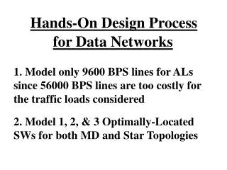
Hands-On Design Process for Integrated V/D Networks 1. Model only 56 KBPS lines since 56000 BPS lines can handle both Voice and legacy data traffic in a CS IVDNet (i.e. AL and TKLT=2 in SDF & Wm=48 Kbps in NLT). 2. Model 1, 2, & 3 Optimally-Located SWs for both MD and Star Topologies.
The Existing Technology for CS-IV/D Networks 1. Several vendors use proprietary voice-digitization algorithms and time-division-multiplexing techniques for sharing a 56-kbps or T-1 digital transmission lines by digitized-voice and data streams. 2. One vendor employs an voice-digitization scheme to fill-up the entire 56-Kbps line with eight (8) voice conversations. Another vendor fills up the same line with 12 voice conversations. The number of conversations on a T-1 line can be computed accordingly for each vendor.
The Existing Technology for CS-IV/D Networks (Contd) 3. This technology is mainly employed by enterprises with small locations with fewer than 8 telephones. 4. The cost of a typical box capable of multiplexing less than 8 digitized voice channels and low speed data sources costs is about $10,000. The total additional CPE cost for a 17-site enterprise is about $170,000 which represents a monthly cost of about $2,000 assuming a 10-year life-cycle and nominal interest rate.
IV/D NETWORKS: The Design Process • Prepare aVHD file using the CPE data • Prepare a NLT file for useful link types • Select the valid tariffs in a TARIFF file • Prepare a valid LINK file if required • Use “Find COGs ”capability for choosing Nsw SW locations for preparing a valid SWF ( Fix NDEC & DECT in SDF for COGs ) • Adjust the required SDF parameters
SDF - The Data-Related Design Parameters • ATP ( Tr analysis type), Wm , ALT, TKLT • UPR,HPR,HTT, R , T , T , K mph np hm pg • IML, RML, BLKL, ICPB ( msg ./block) • N (no. of nodes allowed/ VMPT; valid for cu only Doelz networks), MTKU • F =0 or 1 (for use of Sharma’s exchange opt algorithm for additional optimization)
Updating Design Parameters Follow the same steps in updating the design parameters of SDF and NLT as described for Data Networks. We must nowcreate a new VHD17a to reflect total bps for voice & data. To do that we first need a 8-Col Feasibility Table using output files of VoiceNets. If excess capacity in Col.8 (=Col.7-Col.5) is positive, an IVDNet is feasible.
Making a Feasibility Table 1. Make a 8 Col. Table, with Col. 1= Site# 2. #VG ALs in Col.2 (cf. Exist. Net outp. file ) 3. Original data TI (bps) in Col.3 (cf.VHD17) 4. Voice bps = VG ALs*7000 in Col.4 5. Tot.V/D bps(Col.3+Col.4) in Col.5/VHD17a 6. #56kbpsALs (cf. Output File ) in Col.6 7. Avail. capacity in Col.7 =Col.6*560000
Data Network Design Process 1. Open/View the input file “Files” and enter VHD17a, LINK17, MAPusa , TARIFF, SDF, NAME17, LATA17 and SWF in the proper cells and UPDATE. 2. Open/View the input file “SDF” and update values of ALT=2, TKLT=2, for Leased 56 KBPS lines, ATP=3 for BSC protocol, Wm =48000 bps & BBTF=2.
3. Also use UPR/HPR=9600bps, IML=28, RML=300 bytes, Tnp=10 ms, Thm=4 ms, Tpg= .01 ms/mi, TGF=1, Flk=0, Fflt=0 4. Use SWF with 1 SW at 1, 2 SWs at 1 and 11, 3 SWs at 1, 11 and 2 to create three DataNets with MD topology . 5. Repeat Steps#4 to model DataNets based on Star topology. 6. Tabulate results with REMARKS.
6. Choose the optimum network topology based on your criteria (cost or response Time.) Also show that data comes free. 7. Explain why the MDNets are really star topologies in disguise (Hint: study the output file data)? 8. Include the IVDNet Tabulations with remarks in the MSWord document along with DBF for Optimum IVDNet.