Download
1 / 19
220 likes | 390 Views
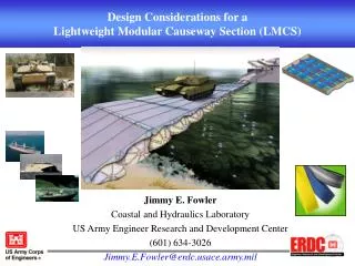
Design Considerations for a Lightweight Modular Causeway Section (LMCS). James N. Pratt Coastal and Hydraulics Laboratory US Army Engineer Research and Development Center (601) 634-2008 James.N.Pratt@erdc.usace.army.mil. Outline. Outline. Objective

E N D
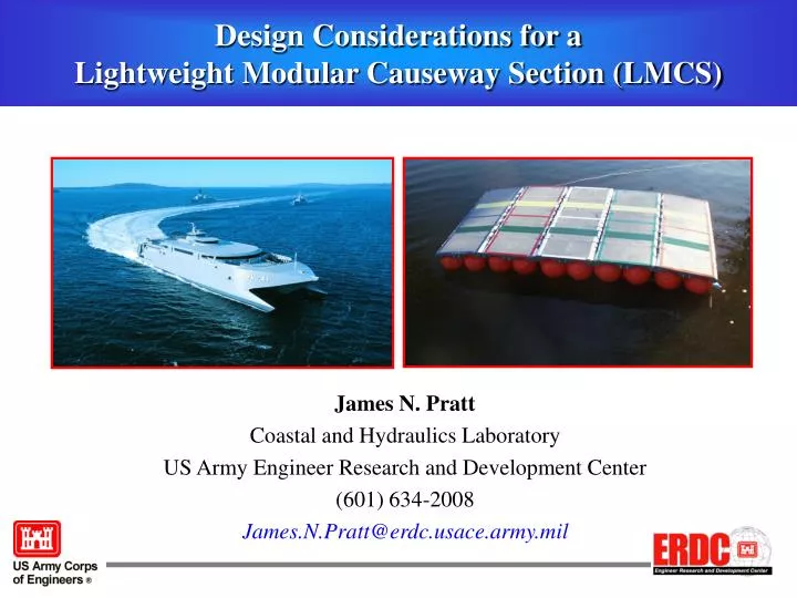
Design Considerations for a Lightweight Modular Causeway Section (LMCS) James N. Pratt Coastal and Hydraulics Laboratory US Army Engineer Research and Development Center (601) 634-2008 James.N.Pratt@erdc.usace.army.mil
Outline Outline • Objective • Desired Causeway Capabilities/Objectives • Key Performance Parameters - Transportability - Durability - Deployability and Recoverability - Survivability - Trafficability - Maintainability • Concept Evaluation Matrices • Questions
To convey significant factors that impact design considerations and concepts for a TSV-transportable rapidly deployable lightweight causeway Objective
Desired Causeway Capabilities/Objectives • Lightweight and compact • ISO Compatible • Rapidly transportable by and deployable from TSV/(HSC?) • Minimal shipboard storage requirements • Provide up to 150-ft of bridging ship-to-shore • Support 70-ton XM1A tank • Operate within sheltered ports and harbors (open coast?, rivers?, ?,?) • Interface with existing and emerging causeway systems (i.e. INLS, MCS, NL) • Interface with JLOTS lighterage and watercraft • Meet requirements for maintainability, reliability, MTBF, service life, etc.,
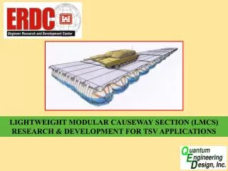
Concepts Considered • Rapid Dredge Fill/ Quay Construction • - Using Hydrobeam Barrier • Modular Causeway Section (MCS) • - All Steel or Composite • Grounded Causeway Concept (GCC) • - Bottom Founded with Hydrobeams • Lightweight Modular Causeway Section (LMCS) • - Floating using Airbeams
Key Performance Parameters Transportability • Weight of system • ISO compatibility • - 20 ft. x 8 ft. footprint • - Material Handling Equipment (MHE) compatibility • TSV storage location • - Last on, first off of first TSV 8 ft. 20 ft.
Key Performance Parameters Deployability and Recoverability • Causeway • Deployment/Recovery method and time/speed • - Weight and size (20-ft segment width limit?) • - Mooring • - Assembling/disassembling • Shipboard vs. sea-state connections/disconnections • Manual vs. automated labor • Opening Size in TSV/HSC for deployment • Vehicle Cargo and Materials Offload • Ramp and causeway interface • - Surface deck deflection • - Ramp system configurations?
Key Performance Parameters Trafficability • Weight and speed of vehicle(s) over causeway • - roll stability • - deck/joint flexure • - sea-state/environmental effects • Number of vehicles on causeway • Entire causeway system • Per stiffened section • Clearance between vehicles • Maximum lane width relative to causeway section width • - M1A1 / M1A2 Abrams is 12 ft. wide
Key Performance Parameters Durability • “Wear and tear” on fabrics • - LMCS Floatation devices along ocean floor • Pneumatic tube fabric • Webbing matrix material • - Deck surface from trafficking • Degradation of mechanical elements (cables, hinges, etc.) • - Fatigue: loading and bending life cycles • Material and design • Other materials/components useful lifespan
Key Performance Parameters Maintainability • In-water vs. shipboard maintenance • Time to repair or replace component (routine vs. emergency) • Number of loading cycles prior to rehabilitation for system/component • Whether or not problem is deemed “critical” - continue with operation or abort • until problem is fixed • - Ex: LMCS air leak(s) • Number • Location relative to load and/or stiffened section
Key Performance Parameters Survivability • Potential system failures (catastrophic or non-catastrophic) • - Air leaks in LMCS floatation devices • Number • Location relative to displaced load and/or stiffened section • Being examined by CHL and QED • - Breakage in joint connections • Number • Location relative to displaced load and/or stiffened section • Other • - Severe weather and wave conditions • - Collision damage
SurvivabilityFloatation Device Air Leak Analysis Manometer Air Intake Air Leak Holes
SurvivabilityFloatation Device Air Leak Analysis Graphical Results
SurvivabilityFloatation Device Air Leak Analysis Preliminary Conclusions • Internal pressure change in floatation device can be adequately predicted for non-catastrophic failure conditions • Additional efforts to examine effects of multiple tubes/applied loads are ongoing • Time of failure due to small arms punctures should be adequate to employ possible failure alternatives for damage control
Evaluation of Options Considered Options Parameters Note: Rapid Dredge Fill Option omitted
LMCS Options Presently Being Evaluated Options Parameters Both options viable at this point
Floatation Device Air Leak AnalysisAdditional Information Numerical Model • Coupling of two gas equations • (1) (2) Subsonic mass flow rate equation for a pressurized gas system Ideal gas equation • Conditions • - Subsonic (low pressure) flow • - Constant vessel volume for theoretical model
Floatation Device Air Leak AnalysisAdditional Information Graphical Results • 1/8-in., 7/32-in., and 1/2-in. air leaks Deviation in theoretical and experimental plots occurs between 16 to 15.50 psia