Download
1 / 101
1.03k likes | 1.25k Views
Unit III Transmission Media. Prepared by Badgujar D D SIT, Lonavala. Transmission medium and physical layer. Classes of transmission media. GUIDED MEDIA.

E N D
Unit III Transmission Media Prepared by Badgujar D D SIT, Lonavala
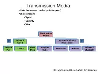
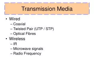
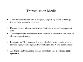
GUIDED MEDIA Guided media, which are those that provide a conduit from one device to another, include twisted-pair cable, coaxial cable, and fiber-optic cable. Topics discussed in this section: Twisted-Pair CableCoaxial CableFiber-OpticCable
Twisted-pair cable • A Twisted pair consists of two conductors ,each with its own plastic insulation, twisted together. • One wire is used to carry signals to the receiver and other is used only as ground reference. The receiver uses the difference between the two. • The noise and crosstalk may affect both wires and create unwanted signal. • If the both wires are parallel, the effect of these unwanted signals is not same in both wires because they are at different locations relative to noise.
By twisting the pairs, the balance is maintained . E.g. In one twist one wire is close to noise another may be away in next twist reverse is the case. • This means the receiver which calculates the difference between the two, receives no unwanted signals.
Unshielded Twisted Pair and Shielded Twisted Pair cables STP is proposed by IBM. It has metal foil or braided mesh covering That encases each pair of insulated conductors. Metal covering improves the quality of cable by preventing the noise . It is heavy And costly
Categories of unshielded twisted-pair cables Proposed by EIA (Electronic Industries Association)
UTP connector (RJ Registered Jack it is keyed connector means can Be inserted by one side only)
UTP performance The performance is measured with attenuation vs frequency. A Twisted Pair can pass wide range of frequencies . However the increasing in freq. the attenuation is also increases sharply. Guage is used the thickness of the wire. Applications : Telephone lines, DSL lines, LAN such as 10 Base T, 100 Base T. etc.
Coaxial carries signal of higher frequencies ranges than those in Twisted Pair. Because the two media are constructed quite differently instead of having two wires. • The outer metallic wrapping serves both as a shield against noise and as the second conductor , which completes the ckt.
Categories of coaxial cables • Coaxial cable is categories by their ratings i.e. RG( Radio government). Each RG denotes the physical specification of the cable i.e. conductor, thickness of inner conductor, construction of the shield, shape of outer casing etc.
Coaxial cable performance As it carries higher freq. as compared to Twisted Pair , but increases the attenuation factor so it requires the Repeater after the specified distance. Applications : TV Network, Telephone Network, Ethernet LAN where RG-58 Cable is used.
Fiber-Optic Cable • A FOC is made of glass or plastic and transmit signals in the form of light. • Light travels in a straight line as long as it is moving through a single uniform substance(medium). If a ray of light traveling through one substance suddenly enters another substance of a different density , the ray changes direction. Fig . shows
Fiber optics: Bending of light ray If the angle of incidence I (the angle the ray makes with the line Perpendicular to the interface between the two substances ) is less than < critical angle , the ray refracts and moves closer to surface I=critical angle the light bends along the surface I>critical angle , the ray reflects (makes a turn) and travles again in the Denser substance. Critical angle is the property of the substance , and its value differs from One substance to another Critical Angle :The smallest angle that will completely reflect a ray within a fibre
Optical fiber • OFC use reflection to guide light through a channel. A glass or plastic core is surrounded by a cladding of less dense glass or plastic. The difference in density of the two material must be such that a beam of light moving through the core is reflected off the cladding of being refracted into it.
Multimode • Multiple beams from a light source move through the core in different paths. How these beams move within the cable depends on the structure of the core.
Multimode step index fiber • The density of the core remains constant from the center to the edges. A beam of light moves through this constant density in a straight line until it reaches the interface of the core and the cladding. At the interface , there is an abrupt change due to a lower density; this alerts the angle of the beam’s motion. The term step index refers to the suddenness of this change, which contributes to the distortion of the signal as it passes through the fiber
Multimode graded- index fiber • It decrease the distortion of the signal through the cable. The word index refers to the index of refraction. A graded index fiber with varying density. Density is highest at centre of core and decrease gradually to the edges.
Single Mode • It uses step index fiber and a highly source of light that limits beams to a small range angles , all close to the horizontal.This is manufacture with small diameter than MM fiber so light propagates at 90 degree to make the propagation of beams almost horizontal. The propagation of different beams is almost identical and delays are negligible.
Fiber types OFC are defined by the ratio of diameter of their core to the diameter of their cladding ,both are expressed in micrometers
Made up of material used in fabrication of bulletproof jackets Figure 7.14 Fiber construction Made up of PVC/ Teflon Used for Cushion for Fiber
Fiber-optic cable connectors Subscriber channel(SC) connector is used for cable TV. It uses Push/pull locking system. Straight-tip(ST) Connector is used for connecting cables to networking devices. MT-RJ (Mechanical Transfer)is a connector that is same a RJ 45 connector. The process is called as splicing
Optical fiber performance It attenuates less . We require 10 times less repeaters when we use FOC Applications : It is used as Backbone network because its wide bandwidth is cost effective. Today, wavelength-division multiplexing (WDM) can transfer data at the rate of 1600Gbps. Some cable TV companies use a combination of optical fiber and coaxial cable thus creating a hybrid network for cost effective purpose.
Advantages of FOC • Higher Bandwidth : FOC is supports dramatically higher bandwidth than either TP and coax. • Less signal attenuation :FOC distance is significantly greater than guided media. A signal can run upto 50KM without repeater. We need repeater after 5KM in TP and coax. • Immunity to electromagnetic interference : Electromagnetic noise cannot affect FOC • Resistance to corrosive materials : Glass is more resistant to corrosive material than copper • Less Weight
Disadvantages of FOC • Installation and Maintenance • Unidirectional Propagation : If we need bidirectional communication then we need two fibers. • Cost
7-2 UNGUIDED MEDIA: WIRELESS Unguided media transport electromagnetic waves without using a physical conductor. This type of communication is often referred to as wireless communication. Signals and normally broadcast through free space and thus available to anyone who has a device capable of receiving them Topics discussed in this section: Radio Waves Microwaves Infrared
Unguided signals can travel from the source to destination in several ways: • Ground propagation: radio waves travel through the lowest portion of the atmosphere close to earth. These low-freq. signals originate in all directions from the transmitting antenna and follow the curvature of the planet. Distance depends on the amount of power in the signal. The greater power, the greater the distance.
Sky propagation: Higher freq radio waves radiate upward into the ionosphere where they are reflected back to earth. This transmission allows for greater distances with lower output power.
Line-of-Sight: Very high freq signals are transmitted in straight lines directly from antenna to antenna. Antenna must be bidirectional, facing each other, and either tall enough or close enough together not to be affected by the curvature of earth.
The radio wave and microwave are divided in Bands These bands are govern by Government Authorities
There is no separation in radio and microwave. The freq. ranging between 3KHz to 1GHz is called radio wave. And freq. between 1 and 300GHz are called microwave. • Radio waves are omnidirectional. When an antenna transmits radio waves, they are propagated in all directions. i.e. sending and receiving antenna do not have to be aligned. A sending antenna sends waves that can be received by any receiving antenna.
Omnidirectional antenna has a disadvantage i.e. one antenna are subject to interference by another antenna that may send signals using same freq./ band. • Radio waves are of low and medium freq. can passes through the walls. This characteristics can be both adv and disadv. • Adv because an AM radio can receive signals inside a building. • Disadv is that we can’t isolate a communication just inside or outside.
Radio wave band is narrow under 1 GHz compared to microwave band. • When this band is divided into sub bands, the sub bands are too narrow ,leading to low data rate for digital communication. • Almost the entire band is regulated by authorities in India TRAI. You must have a permission from governing authority.
Radio waves are used for multicast communications, such as radio and television, and paging systems, cordless phone, AM FM Radio. They can penetrate through walls. Highly regulated. Use omnidirectionalantennas
Microwave • Microwave having freq. between 1GHz and 300 GHz. • These are unidirectional. When an antenna transmit microwave waves, they can be narrowed focused. This means sending and receiving antenna need to be aligned.
Characteristics • This propagation is line-of-sight. Since the towers with the mounted antennas need to be in direct sight of each other, towers that are far apart need to be very tall. • The curvature of earth as well as other blocking obstacles do not allow two short towers to communicate by using microwave • Repeaters are often needed for long distance communication.
VHF microwave cannot penetrate walls. • The band is relatively wide almost 299GHz. Therefore wider subbands can be assigned and a high data rate is possible. This also requires permission from Govt. Authorities.
Antenna • A parabolic dish antenna :is based on geometry of a parabola. Every line parallel to the line of line-of-sight reflects off the curve at angle such that all the lines intersect in a common point called the focus. This dish work as funnel catching a wide range of waves and directing them to a common point.
Antenna • Horn Antenna :looks like a gigantic scoop. Outgoing transmission are broadcast up a stem and deflected outward in a series of narrow parallel beams by curved head.
Applications : Microwaves are used for unicast communication such as cellular telephones, satellite networks,and wireless LANs. Higher frequency ranges cannot penetrate walls. Use directional antennas - point to point line of sight communications.
Infrared • With freq. from 300GHz to 400THz, can be used for short range communication. It has high freq. So can’t penetrate walls . E.g. Remote Control. • We can’t use infrared waves outside a building because the sun’s rays contains infrared waves that can interfere with the communication.
Infrared signals can be used for short-range communication in a closed area using line-of-sight propagation. Infrared Data Association(IrDA) , is a association sponsoring to use infrared for k/b, mouse, printer by providing infrared port.
Switching Datagram Network Virtual-Circuit Network