Download
1 / 3
30 likes | 133 Views
This document provides information on EMCAL SuperModules layout seen from the back/magnet side, towards IP, with detail on sector arrangement and coordinate system according to ALICE-INT-2003-038. It includes rotational and linear numbering for sectors, ideal for LED amplitude plots. Standard view with row as Y-axis and column as X-axis. Detailed view from bottom of CalFrame available as alternative. Coordinates for SM and mapping provided.

E N D
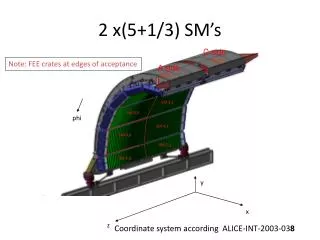
y x z 2 x(5+1/3) SM’s C side SM0,1 Note: FEE crates at edges of acceptance A side SM0,0 SM 3,1 SM 3,0 phi SM 4,1 SM 4,0 SM 5,1 SM 5,0 Coordinate system according ALICE-INT-2003-038
EMCAL, seen from back/magnet side – looking towards IP through EMCAL from the top of the CalFrame. 4 installed SuperModules; sector 0 is the top/highest sector. Standard view. Row as Y-axis, and Column as X-axis (LED amplitude plots). A side C side Sector 1 Phi, (Rotational numbering) Sector 0 Linear numbering (reverse z)
EMCAL, seen from back/magnet side – looking towards IP through EMCAL from the bottom (alternative view) of the CalFrame. Local (row=0,col=0) coordinate SM #1 0 y phi 3 2 (47,0) (0,0) (47,0) (0,0) (47,23) (0,23) (47,23) (0,23) Linear numbering = reverse z C-side A-side