Download

1 / 39
390 likes | 586 Views
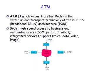
ATM Signaling. Raj Jain Professor of Computer and Information Science The Ohio State University Columbus, OH 43210 Jain@cse.ohio-State.Edu http://www.cse.ohio-state.edu/~jain/. Call Endpoints: Address Formats Call setup/release Traffic Contract: Bandwidth, Quality of Service

E N D
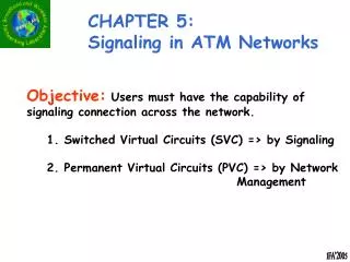
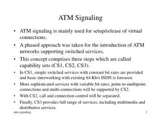
ATM Signaling Raj Jain Professor of Computer and Information ScienceThe Ohio State UniversityColumbus, OH 43210Jain@cse.ohio-State.Edu http://www.cse.ohio-state.edu/~jain/
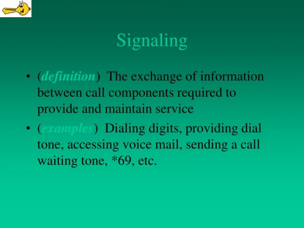
Call Endpoints: Address Formats • Call setup/release • Traffic Contract: Bandwidth, Quality of Service • Signaling Mechanisms: Message formats Overview
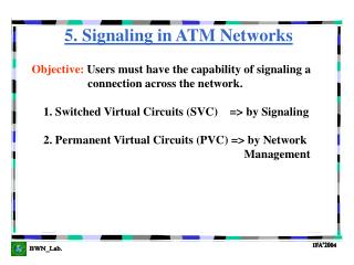
Signaling Standards • Q.931 = Basic Call Control for ISDN • Q.932 = Extends/uses Q.931 for supplementary services (call forwarding, etc) • Q.933 = Q.931 Extension/subset for Frame-relay • Digital Subscriber Signaling System 1 (DSS1) = Call control signaling over the D channel = Q.931 + Q.932 + lower layers • Signaling System 7 (SS7) deals with inside the network while DSS1 deals with outside. • Q.2931 = Q.93B = Basic Call Control for B-ISDN
Signaling Channels • Reserved VPI/VCI • x/1 = Meta-signaling • x/2 = Broadcast signaling (not used initially) • 0/5 = ATM endpoint to local network signaling both point-to-point and point-to-multipoint signaling • x/5 = point-to-point signaling with other endpoints and other networks
Meta-Signaling • Used to setup signaling channels • All meta-signaling messages are one cell longand have VPI/VCI = 0/1 • Sets up 3 types of signaling channels: • Point-to-point • General broadcast • Selective broadcast • Procedures to: • Set up new signaling channels • Release channels • Verify channels
ATM Addresses • ATM Forum specifies three NSAP-like address formats: DCC ATM Format, ICD ATM Format, E.164 ATM Format. NSAP = Network Service Access Point Network supplied End System Supplied Not Used in Routing 39 Data CountryCode (2B) High-Order DSP (10B) End SystemID (6B) Selector(1B) 47 International Code Designator (2B) High-Order DSP (10B) End SystemID (6B) Selector (1B) High-Order DSP (4B) 45 E.164 Number (8 B) End SystemID (6B) Selector (1B) AFI Initial Domain Id Domain Specific Part (DSP)
Addressing • Authority and Format Identifier (AFI)39 = ISO DCC, 47 = British Standards Institute ICD, 45 = ITU ISDN • Initial Domain Identifier (IDI). Domain Specific Part (DSP) • ISDN uses E.164 numbers (up to 15 BCD digits) • ATM forum extended E.164 addresses to NSAP format. E.164 number is filled with leading zeros to make 15 digits. A F16 is padded to make 8 bytes. AFI and DSP are added.
Addressing (Cont) • End System Identifier (ESI): 48-bit IEEE MAC address. • Selector is for use inside the host and is not used for routing. • All ATM addresses are 20 bytes long. • ATM forum removed the division of DSP into areas, etc. • Private networks must support all three formats Type of Number field = UnknownNumbering Plan Indication field = ISO NSAP
Addressing (Cont) • Public networks must support native E.164 and may optionally support three NSAP-encoded formats. For E.164:Type of Number field = International numberNumbering Plan Indication field = Recommendation E.164 • If only native E.164 addresses, subaddress field in signaling messages used to convey private ATM address across. • One Transit network selection possible using carrier identification code field.
NSAP is a Misnomer! • NSAP = Network Service Access Point. Identifies network layer service entry • SNPA = Subnetwork point of attachment. Identifies the interface to subnetwork • SNPA address (or part of it) is used to carry the packet across the network. • CLNP uses NSAP to deliver the packet to the right entity in the host. • ATM uses NSAP-like encoding but ATM addresses identify SNPA and not NSAP. NSAP Network Datalink Physical SNPA
Address Registration • User and switch register addresses using Interim Local Management Interface (ILMI) = Simple Network Management Protocol (SNMP) User Switch ColdStart Trap Initialize GetNext Request What is your address? GetNext Response My address is AA-... Set Request Use prefix +1 614-... Response Sure. Will do. • Similar activities can occur in the reverse direction.
Connection Types • Permanent and Switched • Point to point • Symmetric or asymmetric bandwidth (Uni- or bi-directional) • Point-to-multipoint: Data flow in one direction only. Data replicated by network. • Leaf Initiated Join (LIJ) or non-LIJ
Connection Setup Setup Setup Setup Call Proceeding Call Proceeding Call Proceeding Connect Accept Connect Connect Connect Ack Connect Ack Release Reject Connect Ack Release Complete
Connection Release Release Release Release Release complete Release complete Release complete Or Release Release Release Release complete Release complete Release complete
Connection Release (cont) ConnectionTerminated Release Release Release complete Release complete
Setup Setup Setup Call Proceeding Call Proceeding Call Proceeding Multipoint Setup 1 2 1. Connect to the first party Connect Connect Connect Connect Ack Connect Ack Connect Ack
Multipoint Setup (Cont) 1 2 2. Add the next party. The party accepts. Add Party Add Party Setup CallProceeding Connect Add Party Ack Add Party Ack Connect Ack
Multipoint Setup (Cont) 1 2 3. Add the next party. The party Rejects. Add Party Add Party Setup CallProceeding Release Add Party Reject Add Party Reject ReleaseComplete
Drop Party Drop Party Release Drop Party Ack Drop Party Ack Release complete Release Release Release Release complete Release complete Release complete Multipoint Conn. Release 1 2 1. Root Drops a party 2. Root Drops the last party
Multipoint Release (Cont) 1 3. A party drops out 2 Drop Party Release Drop Party Release complete Drop Party ack 4. Network clears the call ConnectionTerminated Drop Party Release Drop Party Ack Release Release complete Release complete
Setup Setup Setup Call Proceeding Call Proceeding Call Proceeding Connect Connect Connect Connect Ack Connect Ack Connect Ack Leaf Initiated Join (LIJ) 1 2 1. Root sets up a Network LIJ callThe setup message contains LIJ parameters
Leaf Join to an Active Call 1 2 Leaf Setup request Call Proceeding Connect Connect Ack No root notification
Setup Setup Setup Call Proceeding Call Proceeding Call Proceeding Connect Connect Connect Connect Ack Connect Ack Connect Ack Leaf Join to an Inactive Call 1 2 Leaf setup Leaf Setup Leaf setup
Setup Call Proceeding Leaf Join to a non-LIJ Call 1 2 Leaf setup Leaf Setup Leaf setup Add Party Add Party Connect Add Party Ack Add Party Ack Connect Ack
Message Format: Q.2931 8 7 6 5 4 3 2 1 Protocol Discriminator 0000 Lenof Call Ref Flag Call Reference Value Message Type Message (Content) Length Other Information Elements
Message Format • Protocol Discriminator (1 Byte) = Distinguishes Q.2931 messages from other messages08 = Q.931 09 = Q.2931 • Call reference (4 bytes) : Identifies call to which this message is related to. One user may have many calls simultaneously. • Flag = 1 Message is from call reference originator • Flag = 0 Message is to call reference originator • Message Type (2 Bytes): Many types, e.g., connect, call proceeding, setup, release, etc. • Message Length (2 Bytes): Length of contents
Bits 876 Bits 54321 Type 000 Call establishment messages 00010 Call proceeding 00111 Connect 01111 Connect Ack 00101 Setup 01101 Setup Ack 010 Call Clearing Messages 01101 Release 11010 Release complete 011 Information 10101 Status Inquiry 11101 Status 111 Reserved for extension Sample Message Types
Information Element Formats 8 7 6 5 4 3 2 1 Information Element Identifier 1 1Ext CodingStandard IE Instruction Field 2 Flag Res IE Action Ind Length of contents of IE 3-4 5+ Contents of IE
Bits 87654321 Information Element 01110000 Called party number 01110001 Called party subaddress 01111000 Transit network selection 01101100 Calling party number 01101101 Calling party subaddress 01011000 AAL parameter 01011001 ATM Traffic Descriptor 01011010 Connection Identifier 01011100 Quality of Service Parameter 01000010 End-to-end transit delay 01011110 Broadband bearer capability Sample Information Elements
Forward Backward CLP=0 Peak Cell Rate Peak Cell Rate Sustainable Cell Rate Sustainable Cell Rate Maximum Burst Size Maximum Burst Size CLP=0+1 Peak Cell Rate Peak Cell Rate Sustainable Cell Rate Sustainable Cell Rate Maximum Burst Size Maximum Burst Size Bandwidth Contract • User specifies 12 leaky bucket parameters
Q.2931 TCP/IP LMI, SNMP AAL AAL SSCF Q.2130 SAAL SSCOP Q.2110 AAL CP I.363 ATM I.361 SONET, DS1, E1, etc. I.432 Protocol Stacks • Signaling AAL (SAAL) • Service specific coordination function (SSCF): Provides interface to Q.2931 • Service specific connection-oriented protocol (SSCOP): Error and loss recovery • AAL Common Part (AAL CP): Error detection
UNI 3.1 Features • Align with Q.2931 • Use new version of SSCOP
UNI 4.0 Features • Point-to-point and point-to-multipoint calls • Leaf initiated join capability • Notification of end-to-end connection completion • ATM Anycast capability • Multiple signalling channels • Switched virtual path service • Proxy signaling • Frame discard capability • ABR signaling for point-to-point calls • Traffic parameter negotiation
Summary • NSAP address formats • Call setup and release: Point-to-point, point-to-multipoint, Leaf-initiated join • Q.2931 Message formats and information elements • Traffic contracts
References • D. Minoli and G. Dobrowski, “Principles of Signaling for cell relay and frame relay,” Artech House, 1995, 305 pp. • RFC 1237, “Guidelines for NSAP allocation in the Internet” • ATM User-Network Interface Signalling Specifications v4.0 (Jul 1996), ftp://ftp.atmforum.com/pub/approved-specs/af-sig-0061.000.doc (1050 kB)
B-ISDN Recommendations • E.164 Numbering plan for the ISDN era • I.113 B-ISDN vocabulary of terms • I.150 B-ISDN ATM Functional Characteristics, 1993 • I.211 B-ISDN Service Aspects, 1993 • I.311 B-ISDN General Network Aspects, 1993 • I.321 B-ISDN Protocol Reference Model and Its Application, 1993 • I.327 B-ISDN Functional Architecture, 1993 • I.361 B-ISDN ATM Layer Specification, 1993
I.362 B-ISDN ATM Adaptation Layer (AAL) Functional Description, 1993 • I.363 B-ISDN ATM Adaptation Layer (AAL) specification, 1993 • I.413 B-ISDN User-Network Interface, 1993 • Q.2110 B-ISDN SAAL Service Specific Connection Oriented Protocol (SSCOP) • Q.2130 B-ISDN SAAL Service Specific Coordination function (SSCF) • Q.2610 B-ISDN Usage of Cause and Location in B-ISDN user part and DSS2
Q.2931 B-ISDN DSS2 User-network Interface (UNI) Layer 3 Specification for Basic call/connection control • Q.2951 Stage 3 description for number identification supplementary services using B-ISDN DSS2 Basic Call • Q.2961.1 B-ISDN DSS2 Negotiation/Modification: Additional Traffic Parameter Indications • Q.2962, Negotiation of traffic and QoS parameters (during call/connection establishment)
Q.2963, Renegotiation/modification of traffic and QoS parameters (for already established calls/connections) • Q.2964, B-ISDN look-ahead • Q.2971 B-ISDN DSS2 UNI Layer 3 Specificatin for Point-to-multipoint Call/connection control • Q.298x, Multiconnection calls