Download
1 / 52
520 likes | 535 Views
This lecture covers the functions of the data link layer, specific link layer examples, and devices. Topics include digital to analog conversion, framing, physical addressing, flow control, reliable delivery, error detection and correction, security, media access, and quality of service.

E N D
Data-link layer Functions, specific link layers and devices CSE524: Lecture 16
Administrative • Reading assignment • Chapter 5 • Homework #5 • See web site • Sample final exam • See web site • Send me questions to cover by next Monday (November 29th) and I will cover them in class
Where we’re at… • Internet architecture and history • Internet protocols in practice • Application layer • Transport layer • Network layer • Data-link layer • Functions • Digital to analog conversion, Framing, Physical addressing, Demux to upper protocol, Flow control, Reliable delivery, Error detection and correction, Security • Media access and quality of service • Channel Partitioning (TDMA, FDMA, CDMA) • Random access protocols (Slotted Aloha, Pure Aloha, CSMA, CSMA/CD) • Taking turns protocols • Specific link layer examples and devices • Physical layer
DL: Random access MAC protocols • CSMA: Carrier Sense Multiple Access • Listen before transmitting • If channel sensed idle: transmit entire pkt • If channel sensed busy, defer transmission • Persistent CSMA: retry immediately with probability p when channel becomes idle • Non-persistent CSMA: retry after random interval
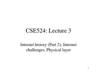
DL: CSMA collisions spatial layout of nodes along ethernet collisions can still occur: propagation delay means two nodes may not hear each other’s transmission collision: entire packet transmission time wasted note: role of distance and propagation delay in determining collision prob.
DL: CSMA/CD (Collision Detection) • Same carrier sensing deferral as in CSMA • Add collision detection • For wired LANs: measure signal strengths, compare transmitted, received signals • Collisions detected within short time • Abort transmission as soon as collision detected to reduce channel waste • Can be used with persistent or non-persistent retransmission
DL: CSMA/CD problems • Can CSMA/CD work over wireless LANs? • Difficult in wireless LANs: receiver shut off while transmitting • Hidden terminal problem
DL: Hidden Terminal effect • A, C cannot hear each other • obstacles, signal attenuation • Neither A or C can tell if they collide at B
DL: CSMA/CA • Use base CSMA • Add acknowledgements • Receiver acknowledges receipt of data • Avoids hidden terminal problem • Avoid collisions explicitly via channel reservation • Sender sends “request-to-send” (RTS) messages • Transmitted without reservation using CSMA with ACKs • Receiver sends “clear-to-send” (CTS) messages • Transmitted without reservation using CSMA with ACKs • Sender sends data packet using reservation • Explicitly indicates length of so others know how long to back off • Used in 802.11 wireless LAN networks
DL: “Taking Turns” MAC protocols • Recall.... • Channel partitioning MAC protocols: • share channel efficiently at high load • inefficient at low load: delay in channel access, 1/N bandwidth allocated even if only 1 active node! • Random access MAC protocols • efficient at low load: single node can fully utilize channel • high load: collision overhead • “Taking Turns” protocols • Best of both worlds?
DL: “Taking Turns” MAC protocols Token passing: • control token passed from one node to next sequentially. • concerns: • token overhead • latency • single point of failure (token) Polling: • master node continuously “invites” slave nodes to transmit in turn • RTS, CTS messages • concerns: • polling overhead • latency • single point of failure (master)
DL: Taking-turns protocols Distributed Polling: • time divided into slots • begins with N short reservation slots • reservation slot time equal to channel end-end propagation delay • station with message to send posts reservation • reservation seen by all stations • after reservation slots, message transmissions ordered by known priority
DL: Media access protocols summary • Managing access to shared media • Channel Partitioning, by time, frequency or code • Time Division, Code Division, Frequency Division • Random partitioning (dynamic), • ALOHA, S-ALOHA, CSMA, CSMA/CD • carrier sensing: easy in some technoligies (wire), hard in others (wireless) • CSMA/CD used in Ethernet • Taking Turns • polling from a central cite, token passing
DL: Specific data-link layers and devices • Specific data-link layers • Ethernet (802.3) • Token Ring (802.5) • WiFi (802.11) • PPP • ATM • X.25 • Frame relay • Specific data-link layer devices • Hubs • Bridges • Switches
DL: Ethernet Metcalfe’s Ethernet sketch “Dominant” LAN technology: • First practical local area network, built at Xerox PARC in 70’s • Cheap: $3 for 100Mbs NIC • Simpler, cheaper than token LANs and ATM • Kept up with speed race: 10, 100, 1000 Mbps
DL: Ethernet's implementation of data-link layer • Digital to analog conversion (Manchester encoding) • Framing (special pre-amble within frame) • Physical addressing (6 byte hardware addresses) • Demux to upper protocol (type field in header) • Flow control (none) • Error detection and correction (CRC-32) • Reliable delivery (none) • Security (none) • Media access and quality of service (CSMA/CD with adaptive, randomized wait)
DL: Ethernet Frames • Sending adapter encapsulates IP datagram (or other network layer protocol packet) in Ethernet frame • Original frame format circa 1970s by Xerox • Not used anymore • Ethernet II frame • Most common type • Other Ethernet frame formats • IEEE 802.3 LLC frame • IEEE 802.3 SNAP frame • Novell Proprietary • Not all compatible with each other
DL: Ethernet II Frame Structure • Preamble – 8 bytes • 7 bytes with pattern 10101010 followed by one byte with pattern 10101011 • Used to synchronize receiver, sender clock rates • Src/Dst Address – 6 bytes • Globally unique, allocated to manufacturers • All adapters listening receive frame, discard if not destined for itself • Type/length – 2 bytes • If field < 1536, then the field indicates packet length • If field > 1536, it indicates higher layer protocol type (mostly IP) • How to determine frame boundaries? • IFS between frames with no transitions indicates frame boundaries • http://www.cavebear.com/CaveBear/Ethernet/type.html • Data – 46 to 1500 bytes • CRC – 4 bytes • Checked at receiver, dropped if doesn’t match • CRC-32 (x32+x26+x23+x22+x16+x12+x11+x10+x8+x7+x5+x4+x2+x+1)
DL: Ethernet: uses CSMA/CD if packet then { A: sense channel if idle then { transmit and monitor the channel; if detect another transmission then { abort and send jam signal; update # collisions; delay as required by exponential backoff algorithm; goto A } else {done with the frame; set collisions to zero} } else {wait until ongoing transmission is over and goto A} }
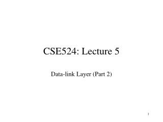
DL: Ethernet CSMA/CD Packet? No Send Sense Carrier Detect Collision Yes Discard Packet b=CalcBackoff(); wait(b); attempts++; attempts < 16 attempts == 16
DL: Ethernet Backoff Calculation • If deterministic delay after collision, collision will occur again in lockstep • If random delay with fixed mean • Few senders needless waiting • Too many senders too many collisions • Exponentially increasing random delay • Infer senders from # of collisions • More senders increase wait time
DL: Ethernet’s CSMA/CD (more) Exponential Backoff: • Goal: adapt retransmission attempts to estimated current load • heavy load: random wait will be longer • first collision: choose K from {0,1}; delay is K x 512 bit transmission times • after second collision: choose K from {0,1,2,3}… • after ten or more collisions, choose K from {0,1,2,3,4,…,1023}
DL: Ethernet CSMA/CD and Packet Size • What if two people sent really small packets • How do you find collision? • Must have a minimum packet size
DL: Ethernet Collision Detect & Packet Size • Min packet length > 2x max prop delay • If A, B are at opposite sides of link, and B starts one link prop delay after A • Jam signal • Jam network for 32-48 bits after collision, then stop sending • Ensures that everyone notices collision
DL: Propagation delay & packet size • Propagation delay determines min. packet size to prevent undetected collisions • Modern 10Mb Ethernet • Minimum packet size calculation • 500m maximum segment length • Can add repeaters up to a maximum 5 segments (2500m) • c in cable = 60% * c in vacuum = 1.8 x 10^8 m/s • ~ 12.5us one-way delay • Add repeater and tranceiver delay • To be safe IEEE specifies a 512 “bit-time” slot for Ethernet = 51.2us • 512 bits = 64 bytes (data payload = 46 bytes)
DL: Minimum packet size • What about scaling? 100Mbit, 1Gbit... • Make network smaller? • Solution for 100BaseT • Make min pkt size larger? • 512bits @ 1Gbps = 512ns • 512ns * 1.8 * 10^8 = 92meters • Gigabit ethernet uses collision extension for small pkts
DL: Ethernet Problems • Ethernet unstable at high loads • Peak utilization = 1/e = 37% • Peak throughput worse with • More hosts – more collisions needed to identify single sender • Smaller packet sizes – more frequent arbitration • Longer links – collisions take longer to observe, more wasted bandwidth
DL: 10Base2 Ethernet • Sifting through the jargon (10Base2) • 10: 10Mbps; 2: under 200 meters max cable length • thin coaxial cable in a bus topology • repeaters used to connect up to multiple segments • repeater repeats bits it hears on one interface to its other interfaces: physical layer device only!
DL: 10BaseT and 100BaseT Ethernet • 10/100 Mbps rate; latter called “fast ethernet” • T stands for Twisted Pair cabling • Nodes connected to hubs or switches in a “star topology” • Max distance from node to Hub is 100 meters based on electrical properties of TP • Smart hubs • Disconnect “jabbering adapter” versus 10Base2
DL: Gbit Ethernet • Use standard Ethernet frame format • Allows for point-to-point links and shared broadcast channels • In shared mode, CSMA/CD is used • shhort distances required to be efficient • Full-Duplex at 1 Gbps for point-to-point links
DL: Token Rings • Packets broadcast around ring • Token “right to send” rotates around ring • Fair, real-time bandwidth allocation • Every host holds token for limited time • Higher latency when only one sender • Higher bandwidth • Point to point links electrically simpler than bus
DL: Token Passing: IEEE802.5 standard • SD, ED mark start, end of packet • AC: access control byte: • token bit: value 0 means token can be seized, value 1 means data follows FC • priority bits: priority of packet • reservation bits: station can write these bits to prevent stations with lower priority packet from seizing token after token becomes free • 4 Mbps • max token holding time: 10 ms (limits frame length)
DL: Why Did Ethernet Win? • Better failure modes • Token rings – network unusable • Ethernet – node detached • Good performance in common case • Volume lower cost higher volume …. • Adaptable • To higher bandwidths (vs. FDDI) • To switching (vs. ATM) • Completely distributed, easy to maintain/administer • Easy incremental deployment • Cheap cabling, etc
DL: IEEE 802.11 Wireless LAN • Wireless LANs: untethered (often mobile) networking • IEEE 802.11 standard: • Defines specific implementations of data-link functions • Framing, error detection, MAC, etc. • Unlicensed frequency spectrum: 900Mhz, 2.4Ghz • Organized into cells called Basic Service Sets • Wireless hosts • Access Point (base station) • Combined to form distribution system
DL: Ad Hoc Networks • Ad hoc network: IEEE 802.11 stations can dynamically form network without AP • Applications: • “laptop” meeting in conference room, car • interconnection of “personal” devices • battlefield • IETF MANET (Mobile Ad hoc Networks) working group
IEEE 802.11 MAC • Allows for several modes • CSMA (with explicit ACK to indicate collision) • CSMA/CA: reservations • Polling from AP
DL: IEEE 802.11 MAC Protocol: CSMA 802.11 CSMA sender - if sense channel idle for DIFS sec. then transmit entire frame (no collision detection) -ifsense channel busy then backoff (random, exponential) 802.11 CSMA receiver if received OK return ACK after SIFS 802.11 CSMA others • NAV: Network Allocation Vector • 802.11 frame has transmission time field • others (hearing data) defer access for NAV time units SIFS and DIFS • Used to separate frames and prioritize them • SIFS < DIFS allows acks to grab channel with higher priority
DL: IEEE 802.11 MAC Protocol CSMA/CA • Same as previous mode but with explicit channel reservation • Send short reservation messages via CSMA to reserve channel • Sender RTS (request to send), Receiver CTS (clear to send) • CTS notifies all hidden stations of sender's reservation • Short messages so that collision less likely and of short duration • Send data unobstructed on reserved channel • End result similar to CSMA/CD
DL: Point to Point Data Link Control • Point-to-point links • One sender, one receiver, one link • Easier than shared broadcast links • No media access control • No need for explicit MAC addressing (ie ARP) • Goal of Point-to-Point protocols • Layer generic “higher-level” data-link layer functions on top of a variety of point-to-point links • Dial-up phone line, DSL, ISDN etc. • Each different link does its own digital-analog conversion (ie provides bits) • Implement common pseudo-link layer on top that implements common functions • Framing, Demux to upper layer, etc. • Examples • PPP (point-to-point protocol) • HDLC: High level data link control (Data link used to be considered “high layer” in protocol stack!)
DL: PPP functions • http://www.rfc-editor.org/rfc/rfc1548.txt • packet framing: encapsulation of network-layer datagram in data link frame • carry network layer data of any network layer protocol (not just IP) at same time • demultiplex upwards • bit transparency: must carry any bit pattern in the data field • error detection: (no correction) • connection liveness: detect, signal link failure to network layer • network layer address negotiation: endpoint can learn/configure each other’s network address
DL: PPP non-requirements Error recovery, flow control, data re-ordering all relegated to higher layers! • no error correction/recovery • no flow control • out of order delivery OK • no need to support multipoint links
DL: PPP Data Frame • Flag: delimiter (framing) • Address: does nothing (only one option) • Control: does nothing; in the future possible multiple control fields • Protocol: upper layer protocol to which frame delivered (eg, PPP-LCP, IP, IPCP, etc) • info: upper layer data being carried • check: cyclic redundancy check for error detection
DL: Byte stuffing in PPP • “data transparency” requirement: data field must be allowed to include flag pattern <01111110> • Q: is received <01111110> data or flag? • Sender: adds (“stuffs”) extra < 01111110> byte after each < 01111110> data byte • Receiver: • two 01111110 bytes in a row: discard first byte, continue data reception • single 01111110: flag byte
DL: Byte Stuffing flag byte pattern in data to send flag byte pattern plus stuffed byte in transmitted data
DL: PPP Data Control Protocol Before exchanging network-layer data, data link peers must • configure PPP link (max. frame length, authentication) • learn/configure network layer information • for IP: carry IP Control Protocol (IPCP) msgs (protocol field: 8021) to configure/learn IP address
DL/NL: Asynchronous Transfer Mode (ATM) • 1980s/1990’s standard for high-speed (155Mbps to 622 Mbps and higher) Broadband Integrated Service Digital Network architecture • Take strengths of IP, learn from its shortcomings • Packet switching good • Packet switching without explicit network-level connections and reservations bad • Packet switching using large headers for small packets bad (voice) • Design new network to address emerging applications while allowing for efficient support for non-real-time data applications • Goal:integrated, end-end transport of carry voice, video, data • meeting timing/QoS requirements of voice, video (versus Internet best-effort model) • “next generation” telephony: technical roots in telephone world • packet-switching (fixed length packets, called “cells”) using virtual circuits • Covered now since it is used mostly as a data-link layer
DL/NL: ATM architecture (whole 9 yards) • adaptation layer: only at edge of ATM network • data segmentation/reassembly • roughly analagous to Internet transport layer • ATM layer: “network” layer • cell switching, routing • physical layer
DL/NL: ATM Adaptation Layer (AAL) • ATM Adaptation Layer (AAL): “adapts” upper layers (IP or native ATM applications) to ATM layer below • AAL present only in end systems, not in switches • Segment (header/trailer fields, data) fragmented across multiple ATM cells • Analogy: TCP segment in many IP packets
DL/NL: ATM Adaption Layer (AAL) [more] User data AAL PDU ATM cell Different versions of AAL layers, depending on ATM service class: • AAL1: for CBR (Constant Bit Rate) services, e.g. circuit emulation • AAL2: for VBR (Variable Bit Rate) services, e.g., MPEG video • AAL5: for data (eg, IP datagrams)