Download
1 / 31
310 likes | 323 Views
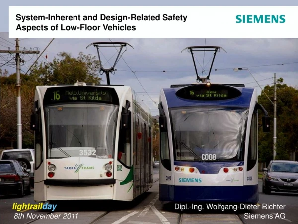
System-Inherent and Design-Related Safety Aspects of Low-Floor Vehicles. lightrail day Dipl.-Ing. Wolfgang-Dieter Richter 8th November 2011 Siemens AG. Design Related Safety Aspects Crash. Side wall.

E N D
System-Inherent and Design-Related Safety Aspects of Low-Floor Vehicles lightrailday Dipl.-Ing. Wolfgang-Dieter Richter 8th November 2011 Siemens AG
Design Related Safety Aspects Crash Side wall ... Front end ...
Crash Impact area investigation Classification of collision damages (statistic evaluation by Siemens Integrated Services) 80% collisions with light road vehicles -> surface damage 20% collisions with other rail vehicles, heavy road vehicles or fixed obstacles -> structural damage Affected areas: 91% of all collision damages repairable by exchange of replaceable components or dent removal/panel beating and paintwork
Crash Element Application and Functional Layout Main targets of the design concept Force • Deformations restricted to areas outside passenger compartment • Controlled degradation of collision energy • Controlled level of deceleration • Anti-climbing prevention Passenger area Regenerative and/or dissipative coupler elements Crash zone of carbody structure Deformation reference: EN 15227
2nd stage (deformation element) impact buffer cellular material cover 1st stage (extended element) GRP Coupler Cover Crash Element Application -Two-stage solution
Crash element application Two-stage solution concept 2. Stage: deformable Crash elements 1. Stage: reversible buffer elements Anticlimber bumper with Anticlimber
Crash element application Interaction of Identical Vehicles • Simplified analysis: collision at 20 km/h Animation
Crash element application Retrictions in Interaction with Conventional Vehicles • Simplified analysis: Low-floor vehicle with conventional LRV In collision with conventional LRV only 2. stage can be applied 100 Animation
Crash element application Side Wall Contact Results • Simplified analysis: deformable barrier with 30 km/h on side wall umax,plast=50 mm Animation
Crash element application Angular Obstacle Contact Results • Simplified analysis: collision with 3t barrier at 25 km/h Animation
Crash Design Solutions Side Wall Tangential Contact Results (Budapest) Caused by a slanting collision with a bus, sidewalls of two vehicle modules had been damaged. Due to the deliberate design of the end sections, the corrugated sheets received damages only, preventing the door posts – as external elements of the passenger compartment core area – from any deformation. The corrugated sheet between door post and end wall prevents the core structure from deformation in case of minor accidents
Concept Related Safety Aspects Crash Multi-articulated vehicles (more than one articulation section between running gears), energy absorbing elements applicable at the vehicle ends only: Single-articulated vehicles (only one articulation section between bogies): Articulation length between two 4-axle cars comparable to permanent coupler length – sufficient space to install additional energy absorbing elements ( ) in the connecting shafts to seperate the vehicle mass portions involved
Concept Related Safety Aspects System-inherent Structural Stress Induction single-articulated 3-module-vehicle single-articulated 2-module-vehicle Single-articulated vehicle: each carbody is supported by ist own bogie. The articulations have to carry only differences in load resulting from unevenly ditributed payload. Therefore only small longitudinal forces were transmitted in the roof area. According to the small additional loads articulation elements and end wall structure can be optimised regarding weight without influencing carbody strength. multi-articulated 3-module-vehicle multi-articulated 5-module-vehicle Multi-articulated vehicle: articulations are heavily laden as total weight of compartment and lion‘s share of payload have to be carried there. In addition, higher longitudinal loads have to be transferred in the roof area. With regard to the restricted installation space between rail and floor level the specific stress of articulation and end wall structure is increased.
Concept Related Safety Aspects System-inherent Lateral Loads in Curves (driving direction) Single-articulated vehicle: stabile running behavior negotiating curves resulting of centrally lateral support of each module. Low sensitivity against lateral deflection proved by test runs in Augsburg. Resulting of the center load the bogies are adjusted tangentially and lateral wheel-rail-loads were distributed evenly. Multi-articulated vehicle: acceptable stability, higher sensitivity against lateral deflection proven by test runs in Augsburg. The parasitic moments [ ] caused by the compartment inertia induce a diagonal wheel-rail contact with increased loads.
source: Schweizer Eisenbahnrevue 11/2010 Concept Related Safety Aspects Derailments Typical aspects of concept derailment behaviour articulation separation front gear derailment source: http://img104.imageshack.us/img104/3554/1998050404cf9.jpg portal gear derailment dynamic derailment
Safety Against Derailment Misalignment Conditions in Daily Operation
Safety Against Derailment Track Requirements Augsburg Perlachberg curve entrance horizontal radius 20 m vertical radius 175 m resulting twist 1 : 136 (between running gears)! (VDV- track layout directive: max. 1 : 300 !)
Safety Against Derailment Misalignment Conditions in Daily Operation (Budapest) Line 37, connection between Line 4/6 and Hungaria-Depot
Flexible:Articulation Solution for Challenging Track Twist Conditions Single-articulated vehicle solution: articulation with lateral rolling freedom allows to negotiate any track twist carbody A carbody B • Results: • Increased safety against derailment in cases of bad track alignment and worn tracks • Significant reduction of car shell stress • Spherical bearings prevent the articulation from torsional loads spherical bearing
Flexible:Articulation Solution for Challenging Track Twist Conditions Video: Ákos Varga, Budapest
21,2 kN 14,7 kN A Concept Influence: Quasistatic Lateral Guiding Force Entering a Curve Multi-articulated car High rotational stiffness of running gears, small deflection angles Single-articulated car Low rotational stiffness of bolsterless bogies, Large deflection angles Quasistatic investigation with standardized mass distribution and 1 m/s² lateral acceleration
Measurement at leading wheel A Concept Influence: Measured Lateral Guiding Force Entering a Curve Multi-articulated car Y in kN High rotational stiffness of running gears, small deflection angles max. 31 kN Single-articulated car Y in kN Low rotational stiffness of bogies, Large deflection angles max. 16 kN Measurements with identical boundary conditions at 1 m/s²
A Concept Influence: Quasistatic Lateral Guiding Force: Parameter Variations larger driver‘s cabin double leaf door at front end double leaf door and larger cabin
? A Concept Influence: Characteristics of Bogie-to-Body Connection Bolster version of conventional and 70%-vehicle concepts; no forced alignment with carbody (comparable to multi-articulated module property), instable behaviour in case of derailment Bolsterless version of single-articulated concept; resilient alignment with carbody (comparable to air spring or flexicoil property), stabilization contribution in case of derailment
Platform Safety Against Derailment Dynamic Derailment of Rear Bogie(s) (Driving direction) Single-articulated car: as the last or the last two bogies derail, centrifugal forces are acting rectangular to the wheel level and try to stop the movement. As long as the towing force continues, the derailed car sections were pulled back to the rails. It was observed that the driver did not realise what happened behind him. (Driving direction) Multi-articulated car: as the last or the last two bogies derail, centrifugal forces are acting rectangular to the wheel level and also try to stop the movement, but the high mass of the bogieless compartment accelerates the derailed section farther off the rails (conventional vehicles with bolster bogies behave in a comparable way). Unfortunately, an additional hazard potential results from the typical platform location at crossings, in line with the swivel range of the derailed sections.
Safety Against Derailment Dynamic Derailment of Rear Bogie(s) trace of flange Melbourne, April 2008: Multi-articulated car in 10 m distance to depot exit (left hand side) Timisoara, Mai 2008: Single-articulated car (during rerailing) after approx. 1 km travel closely beneath the rails
Safety Against Derailment Derailment of Front Bogie by Car Impact Distributiontion of collision damages Lateral impact: 65% of collision impacts occur in the area between front end and first door post 20% of collision results cause severe deformations and affect structural integrity. Lateral loads may exceed the limits of safety against derailment soon in case of straight impact load transmission without any energy absorbing or transformation After left-turning vehicle hits, ROW or red-light ignoring drivers are responsible for accidents with higher lateral impact loads and often serious accident results
Platform Safety Against Derailment Derailment of Front Bogie by Car Impact (Driving direction) Single-articulated car: in case of lateral impact the impetus causes a turning movement of both joined carbodies. The high moment of inertia and the related energy consumption of secondary springs help to reduce the impact load peak remarkably. Not before the end stops are touched, the load limits of safety against derailment may be exceeded (Driving direction) Multi-articulated car: in case of lateral impact the impetus causes an immediate increase of lateral loads between wheel and rail as minimal turning or lateral play is allowed for the end module running gear. Its small mass and moment of inertia favour the load rising. Typically, the vehicle is bending to a circle movement with decreasing radius as far as the articulation angles allow. Unfortunately, also in this case an additional hazard potential results from the typical platform location at crossings, in line with the swivel range of the derailed sections. (see also: http://de.wikipedia.org/wiki/Cityrunner, remark to 2004 accident)
source: http://3.bp.blogspot.com/_TG6mWVFS7Vk/SDMkQ jCPVVI/AAAAAAAAAi0/UhfK3KTIYg4/s1600-h/tram+di+milano+1.JPG source: http://2.bp.blogspot.com/_TG6mWVFS7Vk/SDMkaTCPVWI/AAAAAAAAAi8/hCP3g7OfypQ/s1600-h/tram+di+milano.JPG Safety Against Derailment Derailment of Front Running Gear by Car Impact A small leak will sink a great ship ... Milano 2008 (reference: http://www.tgcom.mediaset.it/ cronaca/articoli/articolo414310.shtml)
Safety Against Derailment Derailment of Front and Center Running Gear by Car Impact source: http://www.siteupload.de/ p993530-unfallborsi08jpg.html source: http://www.siteupload.de/p993530-unfallborsi05jpg.html Just missing a tree ... Dresden 2009 (reference:http://www.sz-online.de/nachrichten/artikel.asp?id=2244379) source: http://www.siteupload.de/p993530-unfallborsi03jpg.html
Dipl.-Ing. Wolfgang-Dieter Richter Siemens AG Text Thank you for your attention!