Download
1 / 38
380 likes | 650 Views
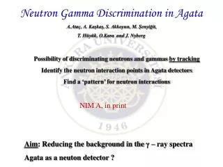
AGATA Advanced Gamma Tracking Array. Determination of position-dependent pulse shapes of Ge detectors N.Goel , T. Engert, J. Gerl, C.Domingo, I. Kojouharov, H. Schaffner,S. Tashenov. 1. Introduction Fundamental parameters of -detector arrays

E N D
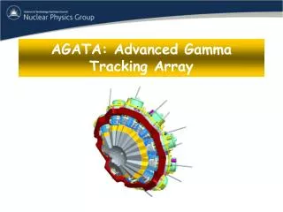
AGATAAdvanced Gamma Tracking Array • Determination of position-dependent pulse shapes of Ge detectors • N.Goel,T. Engert, J. Gerl, C.Domingo, • I. Kojouharov, H. Schaffner,S. Tashenov
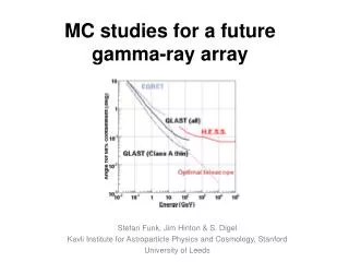
1. Introduction Fundamental parameters of-detector arrays 1. Total photopeak efficiency 2. Energy resolution -> - spectroscopy with relativistic beams 2. AGATA 1. Tracking 2. Pulse shape analysis 3. Scanner at GSI 1. Principle 2. Experimental position dependent pulse shapes 4. Limitation and improvements in first prototype 1. Tests with LYSO crystal scintillator 2. New scanning approach 5. Conclusions Outline of the talk
IntroductionPhotopeak efficiency-high multiplicity -ray cascades SHIELDED DETECTORS COMPOSITE DETECTORS SEGMENTED DETECTORS Ge BGO shields Adjacent Ge crystals operated in ADD BACK mode For high multiplicity M, wrong summing of energies takes place Discrimination between scattered events and individual hits possible with TRACKING Suppress the Compton scattered events 30% of total solid angle covered by Ge
∆Φ IntroductionEnergy resolution: spectroscopy with relativistic beams Intrinsic resolution 2.5keV@ 1.3MeV Doppler Effect@(v/c) ~ 0.5 Reduced solid angle with segmentation ∆Φ • / ~ sin( Φ)• ∆Φ ∆Φ Φ Φ First interaction point has position resolution proportional to the size of segment Analysis of segment pulse shapes gives position resolution even smaller than the size of segment Segmented Detectors
1. Introduction Fundamental parameters of-detector arrays 1. Total photopeak efficiency 2. Energy resolution -Spectroscopy with relativistic beams 2. AGATA 1. Gamma ray tracking 2. Pulse shape analysis Outline of the talk
AGATAAdvanced Gamma Tracking Array • 4π gamma tracking array for nuclear physics experiments at European accelerators providing radioactive and highly intense stable beams 61.08mm 90 mm 52.09mm 60o 10o 10o 34 33 35 31 32 4 3 27 28 5 29 0 30 24 2 26 1 25 18 9 10 22 11 23 6 7 19 8 21 20 13 15 16 17 12 14
AGATAGamma ray tracking • Recognize the individual 3D interaction points • Reconstruct the track of photon using Compton scattering formula • Full energy events distinguished from scattered events => improved photopeak efficiency • Determining the incoming direction with a very good position resolution( 2-3mm) Doppler shift in energy for v/c ~ (0.2 -0.5) E' = E ( 1- (v/c) cos ) Φ
AGATAPulse Shape Analysis For each event, 37x100 samples of preamplifier signals Digital electronics to record the segment signals Radial dependence of pulse shape amplitude(adc units) amplitude(adc units) time(ns) time(ns)
Improvement in Doppler correction with segmentation and PSAIN-Beam test at Cologne, Germany 48Ti(d,p)49Ti 100MeV ∆Φ Energy resolution 1382 keV Det = 32 keV Seg = 11 kev Det = 32kev PSA = 5.5 keV Seg = 11 keV Det = 32keV 1. The center of the detector. 2. The center of the firing segment. 3. Position given by pulse shape analysis. Counts Energy(keV) F. Recchia , ACTA PHYSICA POLONICA B Vol.38(2007)
For interaction at each 3D point inside a segmented detector, there corresponds a unique pulse shape. SCANNERPSA requires a system to scan the detector A data base containing pulse shapes for all possible interaction position inside the detector An efficient system to scan the detector
1. Introduction Fundamental parameters of-detector arrays 1. Total photopeak efficiency 2. Energy resolution - Spectroscopy with relativistic beams 2. AGATA 1. Tracking 2. Pulse shape analysis 3. Scanner at GSI 1. Principle 2. Experimental position dependent pulse shapes 4. Limitation in first prototype 1. Tests with LYSO crystal scintillator 2. New Scanning approach 5. Conclusions Outline of the Talk
22Na→ 2γ, 511 keV 256x scintillator fibres 4x 64 channel PMTs SCANNER PRINCIPLEDetermination of incoming direction of photon Ge detector to be scanned
SCANNER PRINCIPLEDetermination of incoming direction of photon a d Y(arb units) X(arb units) b c X = (b+c)/(a+b+c+d) Y = (a+b)/(a+b+c+d) -> A matrix is reconstructed which gives map of (X,Y).
6 ring slits 42 BGOs 22Na→ 2γ, 511 keV 256x scintillator fibres 4x 64 channel PMTs SCANNER PRINCIPLEDetermination of Z coordinate of interaction position
SCANNER PRINCIPLEEnergy spectra under triple coincidence and Agata energy gate True Event False Event 90o scattering • Even under triple coincidence events its possible to have false events which can be filtered by applying gate on AGATA energy. 511keV 511keV false triggering of BGO Counts Energy(keV)
14 15 7 10 11 6 8 9 amplitude(ADC units) 12 13 14 15 16 17 20 21 18 19 20 21 22 23 time(ns) SCANNER Experimentally determined pulse shapes
SCANNERRadial position informationfrom net charge collecting segment • Pulse rises slowly for interaction occuring close to central or outer electrode. • Pulse for interaction near central electrode is convex while concave for the interaction near outer electrode. • Pulse rises faster for interaction occurring in the middle of the segment. amplitude(ADC units) 1 time(ns) amplitude(ADC units) 1 2 3 1 2 3 time(ns)
SCANNERRadial position information from polarity image charge amplitude(ADC units) time(ns) time(ns) +ve -> Interaction close to outer electrode -ve-> Interaction close to the centre electode
SCANNERAzimuthal position information from amplitude of image charge Pulse shapes from neighbouring segment amplitude(ADC units) time(ns) Segment fired The height of pulses from the segments close to the segment which is fired for a given event is strongly related to the point at which the interaction took place.
SCANNERSummary 2 types of signals have to be analysed Transient charge signal induced in neighbouring segment net charge signal from hit segment Azimuthal position Radial position Radial position is given by rise time and shape of pulse
1. Introduction Fundamental parameters of-detector arrays 1. Total photopeak efficiency 2. Energy resolution - Spectroscopy with relativistic beams 2. AGATA 1. Tracking 2. Pulse shape analysis 3. Scanner at GSI 1. Principle 2. Experimental position dependent pulse shapes 4. Limitation and improvements in first prototype 1. Tests with LYSO crystal scintillator 2. New Scanning approach 5. Conclusions Outline of the Talk
Limitation in the first scanner prototype • 1. Efficiency of fibres??? • Most of the Compton electrons leave the active volume of fibres . • Due to length of Fibre(8cm) light collection suffers. • Much lower count rate contrary to expectation. 1 ct/hr 2.Low count rate problem The true coincidence rate for back segments is about 1 count/hour. BGO 90mm 40ct/hr 10mm
Replacement of fibres with LYSO/BGO Scintillator plate Position sensitive PMT
-> Position resolution of LYSO plate ->Wrapping the upper surface of cyrstal for better light collection Tests with LYSO crystal scintillator
Tests with LYSO crystal scintillatorPOSITION RESOLUTION 3 mm thick 6cm 7.6 cm 6cm Position sensitive PMT SETUP FOR MEASUREMENT OF POSITION RESOLUTION LYSO Reference detector 0.3 mm
Tests with LYSO crystal scintillatorPosition Resolution Energy gate on LYSO and reference detector to filter false events 511 keV 511 keV counts counts Pulse height(channel number) Pulse height(channel number) width 2.3mm counts Y X Y(arb units)
Tests with LYSO crystal scintillatorPosition Resolution surface of LYSO 0.3mm • Distortion near the edges of plate. • Linear central region is approximately 3cm. • An accurate position calibration, allows to determine the spatial resolution (in mm). It has an average value of 2.5 mm. Calculated position of source moved in steps of 1mm Measured position of source reference detector
Tests with LYSO crystal scintillator2. Wrapping material for better light collection TEFLON • Signal amplitude is higher with Enhanced Specular Reflector(ESR) film as compared to Teflon by a factor of ~ 1.32 • (30% light collection improvement) • Higher reflectance increases light collection efficiency. • Finally the upper surface of LYSO is covered with combination of Teflon and ESR. Peak pos.= 346.591 ESR Peak pos.= 457.365 Amplitude
NEW SCANNING APPROACH Ge-Detector Side scanning detector X-Y detector
NEW SCANNING APPROACH Recording the pulse shapes for two positions (a) and (b). Comparing the pulse shapes from two data sets Signal of one set will be identical to signal of other set at the crossing points. Position sensitive Detector Na-22 source 90o a) Na-22 Rotated by 900 b)
1. The next generation of arrays for in-beam -ray spectroscopy will be based on the concepts of pulse shape analysis (PSA) and --ray tracking. 2. Using pulse shape analysis , we can get the position of first interaction point within the hit segment of a multisegmented detector. 3. Experiments have been done already to demonstrate the Doppler correction capability of AGATA detector. 4. GSI implemented a first detector scanner based on principles of PET. 5. Clear capability to obtain the scanning information was demonstrated. 6. Low efficiency of fibre detectors resulted in scanning 10 times slower than originally expected. Conclusions:
7. For this reason , we plan to replace fibres by crystal scintillators. 8. Test done with LYSO coupled to a position sensitive PMT show a position resolution of ~ 2.5 mm and an efficiency of 10% at 511 keV. 9. Pulse shape comparison procedure is proposed for measuring the HPGe detector pulse shapes as a function of the-ray interaction position inside the detector volume. Continued....
POSITION RESOLUTION HAMAMATSU R2486 • Multianode wires crossing each other in X-Y directions. • 12 stage coarse mesh dynode structure. • Anode signals taken from 4 corners labelled as Xa,Xb,Ya,Y • ->variables (X,Y) are calculated using • X =(Xa/Xa+Xb) Y=(Ya/Ya+Yb) • ->A matrix is reconstructed which gives map of (X,Y).
Matrix Reconstruction -> variables (X,Y) are calculated using X = (b+c)/(a+b+c+d) Y = (a+b)/(a+b+c+d) -> A matrix is reconstructed which gives map of (X,Y).
Liverpool Scanning System: 34 BGO's Cs-137 • Limitations in the Liverpool Scanning table: • -> Uncertainities in the position determined in the X-Y direction • due to finite diameter of collimator. • -> Time required to scan along 9 radial lines in steps of 1 mm ~ 90 • days. • -> Count rate in back segments is extremely small, 1ct/ hour