Download
1 / 56
570 likes | 668 Views
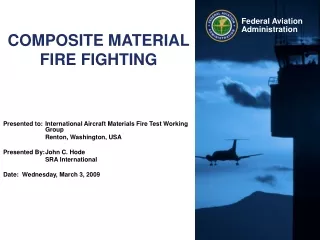
COMPOSITE MATERIAL FIRE FIGHTING RESEARCH. ARFF Working Group October 8, 2010 Phoenix, AZ Presented by: Keith Bagot Airport Safety Specialist Airport Safety Technology R&D Section John Hode ARFF Research Specialist SRA International, Inc. Presentation Outline.

E N D
COMPOSITE MATERIAL FIRE FIGHTING RESEARCH ARFF Working Group October 8, 2010 Phoenix, AZ Presented by: Keith Bagot Airport Safety Specialist Airport Safety Technology R&D Section John Hode ARFF Research Specialist SRA International, Inc.
Presentation Outline • FAA Research Program Overview • Composite Aircraft Skin Penetration Testing • Composite Material Cutting Apparatus • Development of Composite Material Live Fire Test Protocol
FAA Research Program Overview FAA HQ, Washington, DC Tyndall AFB, Panama City, FL FAA Technical Center, Atlantic City, NJ
FAA Research Program Overview Program Breakdown: • ARFF Technologies • Operation of New Large Aircraft (NLA) • Advanced Composite Material Fire Fighting
FAA Research Program Overview Past Projects: • High Reach Extendable Turrets • Aircraft Skin Penetrating Devices • High Flow Multi-Position Bumper Turrets • ARFF Vehicle Suspension Enhancements • Drivers Enhanced Vision Systems • Small Airport Fire Fighting Systems • Halon Replacement Agent Evaluations
Advanced Composite Material Fire Fighting Expanded Use of Composites Increased use of composites in commercial aviation has been well established 12% in the B-777 (Maiden flight 1994) 25% in the A380 (Maiden flight 2005) 50% in both B-787 & A350 (Scheduled) A380, B-787 & A350 are the first to use composites in pressurized fuselage skin
Advanced Composite Material Fire Fighting Research Areas Identify effective extinguishing agents. Identify effective extinguishing methods. Determine quantities of agent required. Identify hazards associated airborne composite fibers.
Composite Aircraft Skin Penetration Testing 3 Types of Piercing Technologies
Composite Aircraft Skin Penetration Testing Objectives • Provide guidance to ARFF departments to deal with the advanced materials used on next generation aircraft. • Determine the force needed to penetrate fuselage sections comprised of composites and compare to that of aluminum skins. • If required forces are greater, will that additional force have a detrimental effect on ARFF equipment. • Determine range of offset angles that will be possible when penetrating composites and compare to that of aluminum skins.
Composite Aircraft Skin Penetration Testing Phase 1: Small-Scale Laboratory Characterization of Material Penetration for Aluminum, GLARE and CRFP (Drexel University) Phase 2: Full-Scale Test using the Penetration Aircraft Skin Trainer (PAST) Device (FAA-TC) Phase 3: Full-Scale Test Using NLA Mock-Up Fire Test Facility (Tyndall Air Force Base)
Composite Aircraft Skin Penetration Testing • Test Matrix Developed • Three Materials: • Aluminum (Baseline) • GLARE • CFRP • Three Thickness’ • Three Loading Rates • Two Angles of Penetration • Three Repetitions
ASPN Penetration/Retraction Process Material deformation & tip region penetration Conical region penetration Cylindrical region penetration Retraction
ASPN Penetration and Retraction Forces NP PP PR NR Constant force is required to perforate aluminum panels after initial penetration Increasing force is required to perforate CFRP and GLARE panels after initial penetration
Maximum Plate Penetration (PP) and Plate Retraction (PR ) Loads at 0.001 and 0.1 in/s P P R R • For Aluminum panels : Retraction load is higher than penetration load, caused by petals gripping the panel upon retraction (due to elastic recovery) • For GLARE and CFRP panels: Penetration load is higher than retraction load - petals remain deformed (due to local damage of composite plies)
Maximum Nozzle Penetration (NP) and Nozzle Retraction (NR ) Loads at 0.001 and 0.1 in/s P P R R • For Aluminum panels : Retraction load is higher than penetration load, caused by petals gripping the panel upon retraction (due to elastic recovery) • For GLARE and CFRP panels: Penetration load is higher than retraction load - petals remain deformed (due to local damage of composite plies)
Petals Formation GLARE (Normal Penetration) Aluminum (Normal Penetration) CRF (Normal Penetration) Aluminum (Oblique Penetration)
Composite Material Cutting Apparatus Purpose Increased use of composite materials on aircraft Limited data available on cutting performance of current fire fighting tools on composite materials Aim to establish a reproducible and scientific test method for assessing the effectiveness of fire service rescue saws and blades on aircraft skin materials
Composite Material Cutting Apparatus Objectives Create an objective test method by eliminating the human aspect of testing Design a test apparatus that facilitates testing of 4’X2’ panels of aluminum, GLARE, and CFRP Measure: Blade Wear Blade Temperature Blade Speed Plunge Force Axial Cut Force Cut Speed Utilize computer software and data acquisition devices to monitor and log data in real time
Composite Material Cutting Apparatus Design Progression
Development of a Composite Material Fire Test Protocol What we knew before this testing…
FedEx DC10-10F, Memphis, TN 18 December 2003 Aluminum skinned cargo flight Traditionally, the focus is on extinguishing the external fuel fire, not the fuselage.
Representative IncidentAir China at Japan Naha Airport, August 19, 2007 4 minutes total video 3 minutes tail collapses ARFF arrives just after tail collapse
Development of a Composite Material Fire Test Protocol External Fire Control Defined Extinguishment of the body of external fire Our question: Will the composite skin continue to burn after the pool fire is extinguished, thereby requiring the fire service to need more extinguishing agent in the initial attack? Cooling of the composite skin to below 300°F Our question: How fast does the composite skin cool on its own and how much water and foam is needed to cool it faster? 300°F is recommended in the IFSTA ARFF textbook and by Air Force T.O. 00-105E-9. (Same report used in both) Aircraft fuels all have auto ignition temperatures above 410°F. This allows for some level of a safety factor.
Creation of a Test Method First objective: Determine if self-sustained combustion or smoldering will occur. Determine the time to naturally cool below 300°F (150°C) Second objective: Determine how much fire agent is needed to extinguish visible fire and cool the material sufficiently to prevent re-ignition. Exposure times of Initial tests: • 10, 5, 3, 2, & 1 minutes • FAR Part 139 requires first due ARFF to arrive in 3 minutes. • Actual response times can be longer or shorter.
Initial Test Set-up Color Video FLIR Color Video at 45 ° Front view
Initial Results Longer exposure times inflicted heavy damage on the panels. Longer exposures burned out much of the resin. Backside has “hard crunchy” feel. Edges however, seem to have most of the resin intact. Edge area matched 1 inch overlap of Kaowool. Test 6, 10 minute exposure Edge View Front (fire side) Back (non-fire side)
Other Test Configurations Tests 22 and 23 The panel was cut into 4 pieces and stacked with ¾ inch (76.2mm) spaces between. Thermocouples placed on top surface of each layer. Exposure time; 1 minute.
Other Test Configurations cont. This configuration not representative of an intact fuselage as in the China Air fire. Measured temperatures in the vicinity of 1750°F (962°C). Wind (in Test 22) caused smoldering to last 52 seconds longer.
Initial Findings Post-exposure flaming reduces quickly without heat source Off-gassing causes pressurization inside the panel causing swelling Internal off-gassing can suddenly and rapidly escape Off-gas/smoke is flammable Longer exposures burn away more resin binder Smoldering can occur Smoldering areas are hot enough to cause re-ignition Smoldering temperatures can be near that of fuel fires Presence of smoke requires additional cooling Insulated areas cooled much more slowly than uninsulated areas
Further Development of Fire Test Protocol Data from first series of tests was used to further modify the protocol development. For example, larger panels and different heat sources were utilized in this round of development. Larger test panels will be needed for the agent application portion of the protocol. Lab scale testing conducted to identify burn characteristics. Testing was conducted by Hughes Associates Inc. (HAI).
Further Development of Fire Test Protocol Lab scale tests • ASTM E1354 Cone Calorimeter • Data to support exterior fuselage flame propagation/spread modeling • ASTM E1321 Lateral Flame Spread Testing (Lateral flame spread) • Thermal Decomposition Apparatus (TDA) • Thermal Gravimetric Analysis (TGA) • Differential Scanning Calorimetry (DSC) • Pyrolysis Gas Chromatograph/Mass Spectroscopy (PY-GC/MS)
Further Development of Fire Test Protocol Secondary test configuration (agent application to be tested at this scale) Three different heat sources evaluated Propane fired area burner (2 sizes) Propane torch Radiant heater Sample panels are 4 feet wide by 6 feet tall Protection added to test rig to avoid edge effects. A representative backside insulation was used in several tests.
Further Development of Fire Test Protocol 12 total tests conducted 9 with OSB 1 uninsulated 8 insulated 3 with CFRP 1 uninsulated 2 insulated
OSB Exposed to Large Area Burnerwith Insulation Backing Large Area Burner On Burner Off – 30 seconds Burner Off – 0 seconds Burner Off – 100 seconds Burner Off – 60 seconds