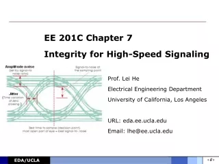
EE 201C Homework 1
EE 201C Homework 1. Fang Gong gongfang@ucla.edu. References. Capacitance Calculation: Formula based T.Sakurai, K.Tamaru, "Simple Formulas for Two- and Three-Dimensional Capacitances," IEEE Trans. Electron Devices ED-30, pp. 183-185


EE 201C Homework 1
E N D
Presentation Transcript
EE 201C Homework 1 Fang Gong gongfang@ucla.edu
References • Capacitance Calculation: • Formula based • T.Sakurai, K.Tamaru, "Simple Formulas for Two- and Three-Dimensional Capacitances," IEEE Trans. Electron Devices ED-30, pp. 183-185 • F C Wu, S C Wong, P S Liu, D L Yu, F Lin, “Empirical models for wiring capacitances in VLSI”, In Proc. IEEE Int. Symp. on Circuits and Systems, 1996 • Table based • J. Cong, L. He, A. B. Kahng, D. Noice, N. Shirali and S. H.-C. Yen, "Analysis and Justification of a Simple, Practical 2 1/2-D Capacitance Extraction Methodology", ACM/IEEE Design Automation Conference, June 1997, pp.627-632 • Field solver • K. Nabors and J. White, "FastCap: A multipole accelerated 3-D capacitance extraction program", IEEE Trans. Computer-Aided Design, 10(11), 1991.
References • Inductance Calculation: • Table based • L. He, N. Chang, S. Lin, and O. S. Nakagawa, "An Efficient Inductance Modeling for On-chip Interconnects", IEEE Custom Integrated Circuits Conference, May 1999. • Norman Chang, Shen Lin, O. Sam Nakagawa, Weize Xie, Lei He, “Clocktree RLC Extraction with Efficient Inductance Modeling”. DATE 2000 • Circuit model and inductance screening • M. Xu and L. He, "An efficient model for frequency-based on-chip inductance," IEEE/ACM International Great Lakes Symposium on VLSI, West Lafayette, Indiana, pp. 115-120, March 2001. • Shen Lin, Norman Chang, Sam Nakagawa, "Quick On-Chip Self- and Mutual-Inductance Screen," ISQED, pp.513, First International Symposium on Quality of Electronic Design, 2000.
References • Inductance Calculation (cont.): • PEEC model and Susceptance model • A.E. Ruehli, “ Inductance calculations in a complex integrate circuit environment,” IBM J. Res. Develop., vol. 16, pp. 470-481, Sept. 1972. • A. Devgan, H. Ji and W. Dai, “How to Efficiently Capture OnChip Inductance Effects: Introducing a New Circuit Element K,” Proc. ICCAD, pp. 150-155, 2000. • Formulas • G. Zhong, and C. Koh. Exact Closed Form Formula for Partial Mutual Inductances of On-Chip Interconnects. ICCD, 2002 • Field solver • M. Kamon, M. J. Tsuk, and J. K. White, “Fasthenry: a multipole-accelerated 3-D inductance extraction program,” IEEE Trans. Microwave Theory Tech., pp. 1750 - 1758, Sep 1994.
2. Further Readings • N. Delorme, M. Belleville, and J. Chilo. Inductance and Capacitance Analytic Formulas for VLSI Interconnects. Electronics letters, 1996 • T. Sakurai. Closed-Form Expressions for Interconnection Delay, Coupling, and Crosstalk in VLSI’s. IEEE Transactions on Electron Devices, 1993 • W. Shi, J. Liu, N. Kakani and T. Yu, "A fast hierarchical algorithm for three-dimensional capacitance extraction", IEEE Trans. CAD, 21(3): 330-336, 2002. • N. Delorme, M. Belleville, and J. Chilo. Inductance and Capacitance Analytic Formulas for VLSI Interconnects. Electronics letters, 1996 • H. Kim, and C. C. Chen. Be careful of Self and Mutual Inductance Formulae. UW-Madison VLSI-EDA Lab, 2001
3. Example for Leff • Calculation effective loop inductance (Leff) of signal trace T2 • According to definition of Leff of T2 • Also, two ground traces have the same voltage drop
Assume all current returns in this block • KCL: • Leff can be solved as a function of partial inductances * L. He, N. Chang, S. Lin, and O. S. Nakagawa, "An Efficient Inductance Modeling for On-chip Interconnects", IEEE Custom Integrated Circuits Conference, May 1999.
3. Homework (due Jan 24) • [1]Given three wires, each modeled by at least 2 filaments, find the 3x3 matrix for (frequency-independent) inductance between the 3 wires. We assume that the ground plane has infinite size and is 10 um away for the purpose of capacitance calculation. l l l T W W W S S H • wire width: W=6um, wire thickness: T=4um, wire length: l=6000um, • wire spacing: S = 10um, distance to ground: H=10um, • Copper conductor:ρ = 0.0175mm2/m (room temperature), • µ =1.256×10⁻⁶H/m, • free space 0=8.85×10 -12F/m
Step 1.1 Discretization and L calculation Discretize 3 wires into 6 filaments. For each filament, calculate its self-inductance with (e.g.) For each pair of filament, calculate the mutual inductance with (e.g.) l l l T W W W S S Filament 6 Filament 1 • Different filaments and formulae may be used for better accuracy.
Step 1.2 Calculate inductance matrix of three wires Mutual Inductance Self Inductance If k=m, Lpkm is the self Lp for one conductor l l l T W W W S S • Lpkm is the mutual inductance between conductor Tk and Tm • Lpij is the mutual inductance between filament i of Tk and filament j of Tm • Lpij can be negative to denote the inverse current direction.
Step 1.3 Capacitance Calculation C2 C4 C1 C3 C5 • C1 and C5 equals to average of those for the following two cases: • single wire over ground • three parallel wires over ground • Total cap below needs to be split into ground and coupling cap
Step 1.4 Resistance Calculation ρ = 0.0175mm2/m l is length of wire A is area of wire’s cross section time
[2] Build the RC and RCL circuit models in SPICE netlist for the above wires. (suggest to use matlab script to generate matrix and thus SPICE netlist)
[3] Assume a step function applied at end-end, compare the four waveforms at the far-end for the central wire using SPICE transient analysis for (a) RC and RLC models and (b) rising time is 20ns, or try to use longer rising time. Suggested Input: VDD 1 0 PULSE(0 1 0 20ns) Output volt 1 20ns 50ns time Input
Waveform from different models RC model RLC model


![EE 201C Homework 4 [Due on Feb 26, 2013]](https://cdn5.slideserve.com/9601754/ee-201c-homework-4-due-on-feb-26-2013-dt.jpg)