Network+ Guide to Networks, Fourth Edition
550 likes | 689 Views
Chapter 7 WANs, Internet Access, and Remote Connectivity. Network+ Guide to Networks, Fourth Edition. Objectives. Identify a variety of uses for WANs Explain different WAN topologies, including their advantages and disadvantages

Network+ Guide to Networks, Fourth Edition
E N D
Presentation Transcript
Chapter 7 WANs, Internet Access, and Remote Connectivity Network+ Guide to Networks, Fourth Edition
Objectives • Identify a variety of uses for WANs • Explain different WAN topologies, including their advantages and disadvantages • Describe different WAN transmission and connection methods, including PSTN, ISDN, T-carriers, DSL, broadband cable, SONET, and wireless Internet access technologies • Compare the characteristics of WAN technologies, including throughput, security, and reliability • Describe the software and hardware requirements for remotely connecting to a network
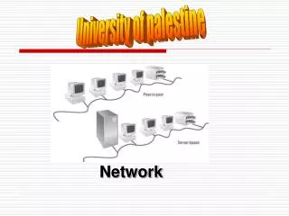
WAN Essentials • Internet is largest WAN in existence • Most WANs arise from need to connect buildings • WANs and LANs similar in fundamental ways • Differ at Layers 1 and 2 of OSI Model • WANs typically send data over publicly available communications networks • Network service providers (NSPs) • Dedicated lines • WAN link: connection between WAN sites (points)
WAN Essentials (continued) Figure 7-1: Differences in LAN and WAN connectivity
WAN Topologies • WAN topologies resemble LAN topologies • Details differ because of: • Distance they must cover • Larger number of users • Heavy traffic • WAN topologies connect sites via dedicated and, usually, high-speed links • Requires special equipment • Links not capable of carrying nonroutable protocols
WAN Topologies (continued) • Bus • Similar to bus LAN topology • Often best option for organizations with few sites and capability to use dedicated circuits • Dedicated circuits make it possible to transmit data regularly and reliably • Ring • Similar to ring LAN topology • Usually use two parallel paths for data • Cannot be taken down by loss of one site • Only practical for connecting few locations
WAN Topologies (continued) Figure 7-2: A bus topology WAN
WAN Topologies (continued) Figure 7-3: A ring topology WAN
WAN Topologies (continued) • Star • Separate routes for data between any two sites • Failure at central connection can bring down WAN • Mesh • Every site interconnected • Fault-tolerant • Full mesh WAN and partial mesh WAN • Tiered • Sites connected in star or ring formations interconnected at different levels • Highly flexible and practical
WAN Topologies (continued) Figure 7-4: A star topology WAN
WAN Topologies (continued) Figure 7-5: Full mesh and partial mesh WANs
WAN Topologies (continued) Figure 7-6: A tiered topology WAN
PSTN • Public Switched Telephone Network (PSTN) comprises entire telephone system • Traffic carried by fiber-optic and copper twisted-pair cable, microwave, and satellite connection • Dial-up usually means connection using PSTN line • Advantages: Ubiquity, ease of use, low cost • Disadvantages: Low throughput, quality, marginal security
PSTN (continued) Figure 7-7: Local loop portion of the PSTN
PSTN (continued) Figure 7-8: A long-distance dial-up connection
X.25 and Frame Relay • X.25: analog, packet-switched technology designed for long-distance data transmission • Specifies Physical, Data Link, Network layer protocols • Excellent flow control • Ensures data reliability over long distances • Comparatively slow • Frame Relay: updated, digital version of X.25 • Does not guarantee reliable delivery of data • Leaves error correction for higher-layer protocols
X.25 and Frame Relay (continued) • Switched virtual circuits (SVCs): connections established when parties need to transmit, then terminated after transmission complete • Permanent virtual circuits (PVCs): connections established before data needs to be transmitted and maintained after transmission complete • Notdedicated, individual links • Committed information rate (CIR): minimum bandwidth guaranteed by service provider • With Frame Relay, pay only for bandwidth required • Throughput sensitive to network traffic
X.25 and Frame Relay (continued) Figure 7-9: A WAN using frame relay
ISDN • International standard for transmitting digital data over PSTN • Specifies protocols at Physical, Data Link, Transport layers • Handle signaling, framing, connection setup and termination, routing, flow control, error detection and correction • Dial-up or dedicated connections • Carries voice calls and data simultaneously on one line • B channel and D channel
ISDN (continued) Figure 7-10: A Basic Rate Interface (BRI) link Figure 7-11: A Primary Rate Interface (PRI) link
T-Carriers • Standards specify method of signaling • Belong to Physical layer • Use time division multiplexing (TDM) over two wire pairs • Divide single channel into multiple channels
Types of T-Carriers Table 7-1: Carrier specifications
T-Carrier Connectivity • Lines require connectivity hardware at customer site and local telecommunications provider’s switching facility • Wiring: • UTP, STP, coaxial cable, microwave, or fiber-optic • STP preferable to UTP (repeaters generally required) • For multiple T1s, coaxial, microwave, or fiber-optic required • For T3s, microwave or fiber-optic necessary
T-Carrier Connectivity (continued) • Channel Service Unit/Data Service Unit (CSU/DSU): • Connection point for T1 line at customer’s site • CSU provides termination for digital signal • Ensures connection integrity through error correction and line monitoring • DSU converts T-carrier frames into frames LAN can interpret and vice versa • Connects T-carrier lines with terminating equipment • Terminal equipment: Switches, routers, or bridges (may be integrated with CSU/DSU)
T-Carrier Connectivity (continued) Figure 7-13: A T-carrier connection to a LAN through a router
DSL • Operates over PSTN • Best suited to local loop • Advanced data modulation techniques allow extraordinary throughput over telephone lines • Physical layer functions
Types of DSL Table 7-2: Comparison of DSL types
DSL Connectivity Figure 7-15: A DSL connection
Broadband Cable • Based on coaxial cable wiring used for TV signals • Asymmetrical • Requires cable modem • Hybrid fiber-coax (HFC): expensive fiber-optic link that can support high frequencies
Broadband Cable (continued) Figure 7-17: Cable infrastructure
SONET (Synchronous Optical Network) Figure 7-18: A SONET ring
SONET (continued) Figure 7-19: SONET connectivity
SONET (continued) Table 7-3: SONET OC levels
IEEE 802.16 (WiMAX) Internet Access • Worldwide Interoperability for Microwave Access (WiMAX): IEEE 802.16a • Frequency ranges between 2 and 11 GHz • Up to 70 Mbps throughput • Potential option for rural and outlying areas
Satellite Internet Access • Satellite Orbits: • Geosynchronous orbit: satellites orbit earth at same rate as earth turns • Uplink: creation of communications channel for transmission from earth-based transmitter to orbiting satellite • Transponder receives uplink signal, transmits it to earth-based receiver in a downlink • Low earth orbiting (LEO) satellites cover smaller geographical area, require less power • Medium earth orbiting (MEO) satellites
Satellite Internet Access (continued) Figure 7-21: Satellite communication
Satellite Internet Access (continued) • Satellite frequencies: • L-band: 1.5 to 2.7 GHz • S-band: 2.7 to 3.5 GHz • C-band: 3.4 to 6.7 GHz • Ku-band: 12 to 18 GHz • Ka-band: 18 to 40 GHz • Satellite Internet services: • Dial return arrangement: receive data via satellite downlink, send data via dial-up connection • Satellite return arrangement: send and receive data using satellite uplink and downlink
Satellite Internet Access (continued) Figure 7-22: Dial return satellite Internet service
WAN Technologies Compared Table 7-4: A comparison of WAN technology throughputs
WAN Technologies Compared (continued) Table 7-4 (continued): A comparison of WAN technology throughputs
Remote Connectivity: Dial-up Networking • Dialing directly into private network’s or ISP’s remote access server to log on to a network • PSTN, X.25, or ISDN transmission methods • Client must run dial-up software • Comes with virtually every OS • Credentials: typically user name and password • Authentication: server compares credentials with database • Remote Access Service (RAS): Microsoft’s dial-up networking software
Remote Access Servers • Routing and Remote Access service (RRAS): Microsoft’s remote access software • Available with Windows Server 2003 NOS and Windows XP client OSs • Enables Windows Server 2003 computer to accept multiple remote client connections • Over any type of transmission path • Enables server to act as a router • Incorporates multiple security provisions
Remote Access Servers (continued) Figure 7-23: Clients connecting with a remote access server
Remote Access Protocols • Serial Line Internet Protocol (SLIP): • Carries only IP packets • Asynchronous transmission • Point-to-Point Protocol (PPP): • Carries many types of Network layer packets • Performs error correction and data compression • Supports encryption • Synchronous or asynchronous transmission • PPP over Ethernet (PPPoE): Standard for connecting home computers to ISP via DSL or broadband cable
Remote Access Protocols (continued) Figure 7-24: Protocols used in a remote access Internet connection
Remote Control • Allows remote user on client computer to control another computer (host) across a LAN or WAN • Host must be configured to allow access • Host may allow clients a variety of privileges • Remote Desktop Software: For Windows OSs • Relies on Remote Desktop Protocol (RDP) • Application Layer protocol • Simple to configure • Can run over any type of connection
Terminal Services • Popular method for gaining remote access to LANs • Terminal server: computer running specialized software allowing it to act as a host • Supplies applications and resource sharing to remote clients • Allows multiple simultaneous connections • Optimized for fast processing and application handling • Terminal services software: Microsoft Terminal Services, Citrix Metaframe • Thin client: workstation using terminal services
Web Portals • Web Portal: Secure, Web-based interface to an application • Places few requirements on client • On host side, Web server supplies application to multiple users upon request • Application must be designed for Web-based access • Requires secure transmission protocols
(VPNs) Virtual Private Networks • WANs logically defined over public transmission systems • Traffic isolated from other traffic on same public lines • Required software usually inexpensive • Windows Server 2003 RRAS • Can be created by configuring special protocols on routers or firewalls connecting VPN sites • Must consider interoperability and security • Tunneling: create virtual connection (tunnel) between two VPN nodes
(VPNs) Virtual Private Networks (continued) Figure 7-27: An example of a VPN