Implementation Example - DSP based Adaptive Array Antenna System -
Implementation Example - DSP based Adaptive Array Antenna System -. Fire Tom Wada Professor, Information Engineering, Univ. of the Ryukyus. DSP based AAA System for OFDM receiver is shown as a implementation example. The System is composed of three parts. OFDM demodulator

Implementation Example - DSP based Adaptive Array Antenna System -
E N D
Presentation Transcript
Implementation Example- DSP based Adaptive Array Antenna System - Fire Tom Wada Professor, Information Engineering, Univ. of the Ryukyus System Arch 2008 (Fire Tom Wada)
DSP based AAA System for OFDM receiver is shown as a implementation example. The System is composed of three parts. OFDM demodulator Adaptive Array Antenna DSP DSP based Adaptive Array Antenna System System Arch 2008 (Fire Tom Wada)
OUTLINE • ISDB-T abstract • OFDM demodulator • Adaptive Array Antenna System • System Design System Arch 2008 (Fire Tom Wada)
The feature of OFDM • Long symbol duration composed by sub-carriers with a guard time • Inter-symbol interference is eliminated • Multi-path distortion to be reduced Terrestrial Digital TV in Japan • BST-OFDM Modulation: 64QAM, 16QAM, QPSK segment 5.6MHz Power Number of sub-carrier 192(Mode2) / 384(Mode3) 1 13 Frequency System Arch 2008 (Fire Tom Wada)
HDTV Broadcast QPSK (1segment) 64QAM (13segment) Modulation Data Rate • 370Kbps • 15Mbps Availability 2003 2005/E Usage Home-use Mobile Quality/Mobility High / Low Today’s Broadcast (ISDB-T) Handheld Low / High System Arch 2008 (Fire Tom Wada)
A D C Symbol Reform F F T Channel Estimator E Q F E C Synchronizer F F T Channel Estimator Synchronizer Simplified OFDM Receiver Model • Accurate and Agile Synchronizer • Broad Dynamic Range of FFT • Sophisticated Channel Estimation System Arch 2008 (Fire Tom Wada)
Tg Data: 8K points COPY + Head GI TailGI GI: 512 points 8704 points Mode3:GI(1/16) Guard Interval of OFDM signal • In order to prevent (n-1) delay symbol from interfering to n symbol,GI is pre-appended as a copy of the tail of the Effective OFDM symbol. • We call Head-GI and Tail-GI. • Head-GI and Tail-GI will be used in the AAA signal processing. Effective OFDM symbol=1 / f0 Tg System Arch 2008 (Fire Tom Wada)
? combined Adaptive Array Antenna • Using multiple Antenna, signals are combined to reproduce a clean signal . • Complex multiply and complex addition is used. • DSP to calculate those weights (wn). Desired Signal Delayed Noisy Interference System Arch 2008 (Fire Tom Wada)
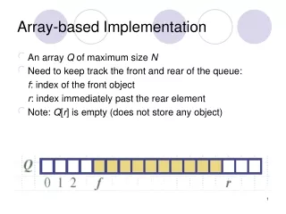
AAA signal processing Using DSP,Coefficients are calculated K-elements Antennas CombinedOutput Sample Output Signals (Tail GI period) Sample Input Signals (Head GI period) System Arch 2008 (Fire Tom Wada)
Adaptive Algorithms • Asynchronous • Maximum Ratio Combining_Asyn • Synchronous • Maximum Ratio Combining_Syn • Sample Matrix Inversion • Power Inversion • Adaptive Beam-forming • Emphasize the desired Signal • Adaptive Null Steering • Suppress interference signal Since the algorithm should be flexible, S/W approach is better! System Arch 2008 (Fire Tom Wada)
symbol crosscorrelation combined Head GI OFDM symbol crosscorrelation Tail GI combined MRC(Maximum ratio combining) • Coefficients are calculated by cross-correlation of input signals and combined signal. • MRC_ASYN • MRC_SYN Head_GI = Tail_GI property is used. System Arch 2008 (Fire Tom Wada)
inversion autocorrelation Head GI OFDM symbol crosscorrelation Tail GI combined SMI(Sample Matrix Inversion) • SMI needs reference signal • Here Head_G I= Tail_GI property is used. System Arch 2008 (Fire Tom Wada)
Tail GI Head GI OFDM symbol - autocorrelation inversion PI(Power Inversion) • PI algorithm can suppress maximum signal.=( Power Inversion) • Here, we try to suppress the Difference of Head_GI and Tail_GI. System Arch 2008 (Fire Tom Wada)
Desired Delay Interferenece 60° Weight data HostPC Beam Pattern 15° -30° DSP interface DSPBoard AAA-OFDMSYSTEM -75° Evaluation Condition System Arch 2008 (Fire Tom Wada)
Adaptive Beam-forming MATLAB Simulation[MRC_ASYN, MRC_SYN)] MRC_ASYN MRC_SYN System Arch 2008 (Fire Tom Wada)
Adaptive Beam-forming Adaptive Null Steering MATLAB Simulation[SMI,PI] SMI PI System Arch 2008 (Fire Tom Wada)
Reflec-tion etc. DSP interface GI Adaptive processor SYSTEM DESIGN OFDM receiver Tuner Complex data System Arch 2008 (Fire Tom Wada)
DSP based AAA System SampleHead&Tail GI signal 225MHz (1350MFLOPS) C6713DSPFloating Point DSP System Arch 2008 (Fire Tom Wada)
512points * 4branches Head GI Tail GI EMIF GPIO HostPC DSP_RUNDSP_VALID EXT_HWI[1-3] TMS320C6713 DSP[Texas Instruments Inc, Floating point DSP] • 225MHz(1350MFLOPS) • Internal Memory C6713DSP Program Area:4KB Data Area:4KB SRAM:192KB Peripheral • 32bit EMIF • GPIO System Arch 2008 (Fire Tom Wada)
1 antenna OFDM Receiver IFFT EQ BaseBand Conversion CLK error compensation RF error compensation Complex data SYNC FFT Tuner A/D TMCC CR D/A AGC System Arch 2008 (Fire Tom Wada)
4 antenna DSP based AAA OFDMreceiver IFFT EQ SYNC BaseBand Conversion CLK error compensation RF error compensation A/D Complex data FFT Tuner A/D TMCC A/D CR A/D D/A AGC Head & Tail GI4branches Weight data DSPInterface TMS320 C6713 DSP System Arch 2008 (Fire Tom Wada)
DSP Controll Logic Signal Transfer Logic DSP Interface From 4 Branch Signal To Weight DSP interface Write Data Logic Buffer RAM Parameter4w x 32b FF4w x 32b EXTHWI1-3 VALID DSP_RUN BkSel2 Y0C[0:511] RESET BRAMC8kw x 32b Y1C[0:511] Y2C[0:511] Y3C[0:511] DSP Board GP_IO CE2 CE1 SDRAM(option) FLASH TI DSP C6713 CLK LED DIP System Arch 2008 (Fire Tom Wada)
CPU is used forData transfer H/W – S/W interface timing diagramw/o DMA ASYNC mode SYNC mode System Arch 2008 (Fire Tom Wada)
CPU core is free for Data transfer EDMA memory access does NOT conflict with CPU core memory access. Performance Optimization • Let processor core to concentrate weight calculation! • EDMA (Enhanced Direct Memory Access) • Double memory buffer in DSP System Arch 2008 (Fire Tom Wada)
2-port BRAM Writer access toPong Buffer Writer(OFDM receiver) Ping Writer access toPong Buffer Reader(DSP) Pong Double Buffer • 2 bank Ping-Pong buffer • 2-port RAM is used for Real Implementation. • Each Port can operate at Different CLK frequency. System Arch 2008 (Fire Tom Wada)
Data Transfer during CPU H/W – S/W interface timing diagram System Arch 2008 (Fire Tom Wada)
X0Br1[0-511] X0Br2[0-511] X0Br3[0-511] X0Br4[0-511] X1Br1[0-511] X1Br2[0-511] X1Br3[0-511] X1Br4[0-511] W0Br1 W0Br2 W0Br3 W0Br4 Before Optimization EMIF Head GI Head GI Head GItransferredusing CPU 1 0 Tail GItransferred using CPU TailGI TMS320C6713DSP Tail GI MRCASYN MRCSYN SMI PI 1 ISRAM address 11 CPUDataTransfer parameter Parameter Weight Weightdata System Arch 2008 (Fire Tom Wada)
X0Br1[0-511] X0Br2[0-511] X0Br3[0-511] X0Br4[0-511] X1Br1[0-511] X1Br2[0-511] X1Br3[0-511] X1Br4[0-511] W0Br1 W0Br2 W0Br3 W0Br4 After Optimization EMIF EDMA Head GI Head GI Head GIReceived Channel 0 1 1 0 Head GIReceived Channel 0 TailGI 1 Ping Buffer Pong Buffer TMS320C6713DSP Tail GI MRCASYN MRCSYN 1 SMI PI ISRAM address 12 Ping Buffer Pong Buffer parameter Parameter Weight Weightdata System Arch 2008 (Fire Tom Wada)
1 EDMA per Symbol 2 EDMA per Symbol CPU Speed Comparison MAX 57% Speed Enhancement System Arch 2008 (Fire Tom Wada)
Measured Results[MRC_ASYN, MRC_SYN)] MRC_ASYN方式 MRC_SYN方式 BER: 1.30E-02 BER: 4.3E-03 System Arch 2008 (Fire Tom Wada)
Measured Results[SMI,PI] SMI方式 PI方式 BER: 6.60E-03 BER: 2.40E-03 System Arch 2008 (Fire Tom Wada)
TUNER AGC ADC DSP board JTAGEmulator SYSTEM PHOTOGRAPH 4 antenna • Video System Arch 2008 (Fire Tom Wada)
ALL SUBJECTS ARE FINISHED! • THANK YOU!!! System Arch 2008 (Fire Tom Wada)