Download
1 / 11
110 likes | 290 Views
Alarms and interlocks handling in the FSM environment. Nothing but admiration for the excellent result!. The standardization of the FSM state diagram; The FSM error states and their recovering procedures; An overview on the CAEN, WIENER and ISEG interlocks inputs Conclusions. Hypernet. wise.

E N D
Alarms and interlocks handling in the FSM environment Nothing but admiration for the excellent result! • The standardization of the FSM state diagram; • The FSM error states and their recovering procedures; • An overview on the CAEN, WIENER and ISEG interlocks inputs • Conclusions Hypernet
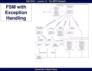
wise The Standardization in the FSM environment The FSM approach in designing a CS allows for to define an “Insulation layer” between the operator and the detector during the detector operation. Except the highest state diagram, the underlying others may be unknown to the operator. However, to let any ALICE operator, to accomplish a recovering procedure (e.g. form the ERROR state) on different sub-detectors but on the same sub-system (HV, LV…), then it would be wise to have a common approach in designing the state diagram also for the sub-systems. If welcomed at the level of sub-system, the FSM standardization is mandatory at level of sub-detector operation. This is intended to let the ALICE DCS layer to send the same series of command to operate simultaneously all the sub-detectors and easily calculate the overall ALICE logical state.
13.2. Alarm Handling from the JOCOP FW sub-project guidelines and convention document Following the guidelines of the AWG the intention of an alarm is to bring an anomaly situation to the attention of an operator and as such alarms are considered to be messages which are displayed to the operator via the alarm display and that are logged. An alarm does not initiate an action. Should an action be required then this should be handled within the FSM. An alarm has several properties: · Its Origin, which is used to identify the source of an alarm. · Whether or not the alarm requires acknowledgement. · Its Severity Level, which is used to characterise the seriousness of the alarm. · Its Dependencies on other alarms. · Certain Additional Details about the alarm.
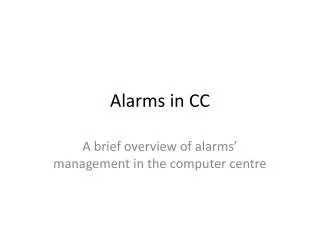
Alarm notification in PVSS and the FSM system recovering System RECOVERING on alarms in FSM ALARM NOTIFICATION in PVSS Alarm sources
An example of HV system recovering on different alarm severity • On the PVSS warning the operator is prompted via a color coded message on the MMI. No FSM automatic actions are taken. • ERROR_REPAIR: this is a FSM state that becomesactive, at the level of the module Device Unit, as soon as one or all the HV linked channels are in trip. Then according to the number of the tripped channels, the module is automatic switched off and then the operator is allowed to recover the module from the fault condition. It doesn’t activate the highest HV Control Unit ERROR • ERROR: this is a FSM state that becomes active, at the level of HMPID HV CU, on the occurrence of the SY1527 failure (fan failure, un-calibrated board, external interlock..) or on more than 3 modules in the ERROR_REPAIR state. In this case all the HMPID HV is switched off and the ERROR state notified to the ECS for the sub-detector recovering procedure.
Interlocks The cross-system interlock activation represents the most sever alarm condition for a subsystem. In this case the DCS goes directly in the major ERRORstate. This must be propagated to the ECS level to start the recovering procedure for that sub-detector. ISEG HV modules Safety loop=Interlock input : 5mA < Is< 20 mA HV ON; Is< 5 mA HV OFF CAEN SY1527 Kill input: all the channels switches OFF (regardless RMPDW setting), both TTL/NIM signal are accepted. Interlock input:. Both Open/close contact logic available Remote Power On: 12V 50 mA WIENER PL500 Interlock input : + 5 V (on 500 W normally open relay) to keep ON the power unit. Removing the 5 V, the PS switches OFF The levels and logics accepted by the PS units suggest as Interlock line source a TTL signal provided via a (normally open) kept closed relay when the source system is OK. On the system failure (interlock active) the interlock relay has to be released, removing the TTL level from the PS units that consequently will switch OFF. This logic is now adopted by CERN group providing the GAS control systems.
Suggestion/proposal • Dedicated meetings • To define the standard HV and LV state diagrams • To define the FSM ERROR states with respect to the Alarm severity • to start the FSM design for each sub-detector. • All the HMPID DCS software will be made available on the web as a DCS example
Conclusions • In order to standardize the sub-system operation and the error recovering procedure (Hv, LV,…) on the different ALICE sub-detectors, it is wise to standardize as much as possible the subsystem state diagrams along with the sub-detector state diagrams. • So far, on the ERROR recovering procedure there are the following examples: • According to the Alarm severity in the HMPID DCS there are two error states: ERRO_REPAIR and ERROR; • In the TPC DCS just one: ERROR . • An overview on the Interlock inputs on the CAEN, WIENER and ISEG power supplies, has shown that a TTL signal, provided via a normally open relay, kept close by the interlock system source on the running condition, can provide a commonly accepted signal level and logic.