
Embedded System Introduction
E N D
Presentation Transcript
Embedded System Introduction Dr. I. Arul Rayappan Associate Professor of Physics, St. Joseph’s College (Autonomous), Tiruchirappalli-620 002.
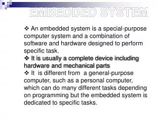
What is an embedded system? According to the Institution of Electrical Engineers, "A general purpose definition of embedded systems is that they are devices used to control, monitor or assist the operation of equipment, machinery, or plant. 'Embedded' reflects the fact that they are an integral part of the system..." An embedded system is a special-purpose computer system, which is completely encapsulated by the device it controls. An embedded system has specific requirements and performs pre-defined tasks, unlike a general-purpose personal computer.
Microcontrollers and Embedded System Embedded Systems are a combination of Hardware (microcontrollers) and Software (developed in assembler, c, c++…) designed to perform a specific function An embedded product uses microcontrollers to do one task and one task only.
What is a Microcontroller? A microcontroller (often abbreviated MCU) is a single computer chip (integrated circuit) that executes a user program, normally for the purpose of controlling some device, hence the name microcontroller. The program is normally contained either in a second chip, called an EPROM, or within the same chip as the microcontroller itself. A microcontroller is normally found in devices such as microwave ovens, automobiles, keyboards, CD players, cell phones, VCRs, security systems, time & attendance clocks, etc.
Microprocessor Vs Microcontroller Microcontrollers are used in devices that require some amount of computing power but donot require as much computing power as that provided by a complex (and expensive) 486, Pentium, i3 .. system which generally requires a large amount of supporting circuitry (large motherboards, hundreds of megabytes of RAM, hard drives, hard drive controllers, video cards, etc). A microwave oven just does not need that much computing power. Microcontroller-based systems are generally smaller, more reliable, and cheaper. They are ideal for the types of applications described above where cost and unit size are very important considerations. In such applications it is almost always desirable to produce circuits that require the smallest number of integrated circuits, that require the smallest amount of physical space, require the least amount of energy, and cost as little as possible.
Microcontroller Ext int interrupt Address Bus (Uni dirctional) CPU Data Bus (Bi directional) Control Lines OSC
Microcontroller Ext int interrupt Timer0 Timer1 ROM RAM CPU Bus control 4 I/o ports Serial port OSC
Microcontroller Manufacturing Companies • There are FOUR major companies manufacturing • 8 bit controllers • Motorola (6811) • Intel (8051 MCS51) • Zilog (Z8) • PIC (16X____) Microchip
Port Organization of MCS51 Port 1 P1.0 – P1.7 Port 0 P0.0 – P0.7 P1 P0 Port 3 P3.0 – P3.7 Port 2 P2.0 – P2.7 P3 P2
Port Assignments Port 0 : Input/Output Port & AD0-AD7 for ext memory Port 1 : Input/Output Port Port 2 : Input/Output Port & A8-A15 for ext Memory Port 3 : Input/Output Port P3.0 : RxD P3.1 : TxD P3.2 : INTO’ P3.3 : INT1’ P3.4 : T0 P3.5 : T1 P3.6 : WR’ P3.7 : RD’
A Circuit using 89c51 40 +5V Pin 40 +vcc 20 Gnd 9 Reset 18 OSC1 19 OSC2 31 Ext Access 9 89c51 31 18 19 GND 20
Input circuit Output circuit
ALARM_1 Program source code ORG 0000h ; define memory start address 000 ; Initialise the I/O ports MOV P3, #0ffh ; write all ones to P3 to use as an input port MOV P1, #00 ; all zeros to put P1 in a known output state POLL: MOV A, P3 ; read P3 to accumulator CJNE A, #00h, ALARM ; if not all zeros then jump to ALARM LJMP POLL ; else loop back to POLL ALARM: SETB P1.7 ; enable the BELL by setting P1.7 high END_LOOP: LJMP END_LOOP ; program just loops around here END ; end of program
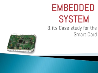
Interactive Vehicle Tracking System It is a system which can track the vehicles for its movement through out the trip with GPS And GPRS. The data collected at different data points are stored at the vehicle itself and in the computers of respective data points then to the server. The Data are vehicle number, started time, stop time, Fuel at, Date, Fuel type, Qty, Amount, Balance, Driver ID ….. The Data Points are the places where the interactive RF transmitter and receivers are fixed say BPCL fuel stations.
At the data points GPS & GPRS based RF transmitter and receivers (RF System) are connected to a computers GPS system is capable of interacting over area of 1 square metre The GPS will transmit the data in a periodic interval continuously from the data point
Server Block diagram of data locker Receiver Memory D i s p l a y GPS & GPRS Micro Controller Transmitter sensors Start/stop alarm Load Fuel
Block diagram of data point Server Receiver GPS & GPRS SMS Micro Controller Printer Transmitter Pump Pump link circuit
Advantages • Compatible with any SMART cards • Data is stored at data point (fuel station computer) and at the vehicle • Vehicle owners can verify trip data from their office • Data can be online with server • Data can be on auto SMS from vehicle(GSM/CDMA/GPRS) • Owners of the vehicles and dealers are not at the dark, but given with lot of information about their vehicles for analysis • 100% automated system