Download
1 / 21
210 likes | 473 Views
Design and Application of Power Optimized High-Speed CMOS Frequency Dividers. 3. 3. Outline. Background. 1. Approach. 2. Application. 3. Conclusion. 4. A Application. C Solution. PLL DDS RF circuit …. Circuit Partition Architecture Select FF.

E N D
Design and Application of Power Optimized High-Speed CMOS Frequency Dividers
3 3 Outline Background 1 Approach 2 Application 3 Conclusion 4
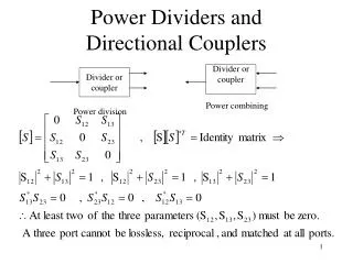
A Application C Solution PLL DDS RF circuit … Circuit Partition Architecture Select FF Background-high speed frequency divider B Challenge High Frequency P = CVdd2fα
Approach-register based frequency dividers Divide by two Counter-based approach require a lot of registers First stage 1.Sense Amplifer have small Tdq delay 2.Only two FF 3.Only one differential logic control state
Approach-register based frequency dividers Divide by 5 Second Stage 1.MSFF have small power dissipation 2.Only three MSFF 3.Only one logic eliminate forbidden state
Approach-register based frequency dividers 90-nm technology Result 190 uW/GHZ Reduce 3/4 1.1V Power Supply 5.5GHz
Approach-high speed IQ divider architecture Conventional IQ divider with 90 degree phase skew • Edge triggered FF Data to Q delay is to long Conventional MS latchBe at risk of race condition Single ended structure Cannot produce precise phase skew signal • Fully Differential high speed low power divider based on CMOS logic
Approach-high speed IQ divider architecture First Part: Pulse Generator • High frequency input signal Interconnection is simpleDifferential feedback structureLow error rate • Low power dissipation • No static current source • Disadvantage
Approach-high speed IQ divider architecture Second Part: Post processing stage Signal diagram
Approach-high speed IQ divider architecture PSPICE simulation Conditions: 1 Voltage 7GHz input signal The worst process corner
Approach-high speed IQ divider architecture Advantages The complete circuit does not contain any current sources The circuit does not require full swing signals at the internal nodes. The circuit is absolutely symmetric.
Approach-performance evaluation Implementation of divider in 90 nm CMOS technology Structure : Two sense-amplifiers One shifter core Two SR latches The high accuracy of the phase skew can be achieved only if the symmetry of the circuit is maintained in the layout of the divider block(wiring and layout).
Approach-performance evaluation The divider consumes 0.36 mW/GHz at 1.0 V and 1.02 mW/GHz at 1.6 V at a maximum operation frequency of 12.4 GHz. Sensitive curves
Application-phase rotator and application in dual modulus pre scaler Conventional approach Additional phase synthesizer Asymmetric layout
Application-phase rotator and application in dual modulus pre scaler Proposed divider Dynamic coupling stage phase generator and selector in one circuit block Symmetric architecture
Application-phase rotator and application in dual modulus pre scaler Pre scaler using proposed IQ divider master-slave toggle flip-flops
Application-phase rotator and application in dual modulus pre scaler Performance
Application-signal generation for IQ signal mixer Process variations and supply noise do not degrade the signal quality excessively Performance
Conclusion A high-speed low-power divider topology without static current sources has been proposed for a 90-nm low-power CMOS technology. A maximum input frequency of 12.4 GHz is achieved with a maximum power consumption of 1.02 uW/GHz. The fully symmetric circuit allows for the generation of output signals with a highly precise phase skew of 90 deg.