Download
1 / 36
370 likes | 478 Views
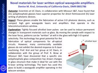
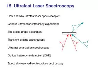
Explore cutting-edge ultrafast laser systems and techniques like Ti:Saph oscillator, NOPA, and pump-probe spectroscopy for studying elementary reactions in biology. Learn about photon counting, fluorescence spectroscopy, and more.

E N D
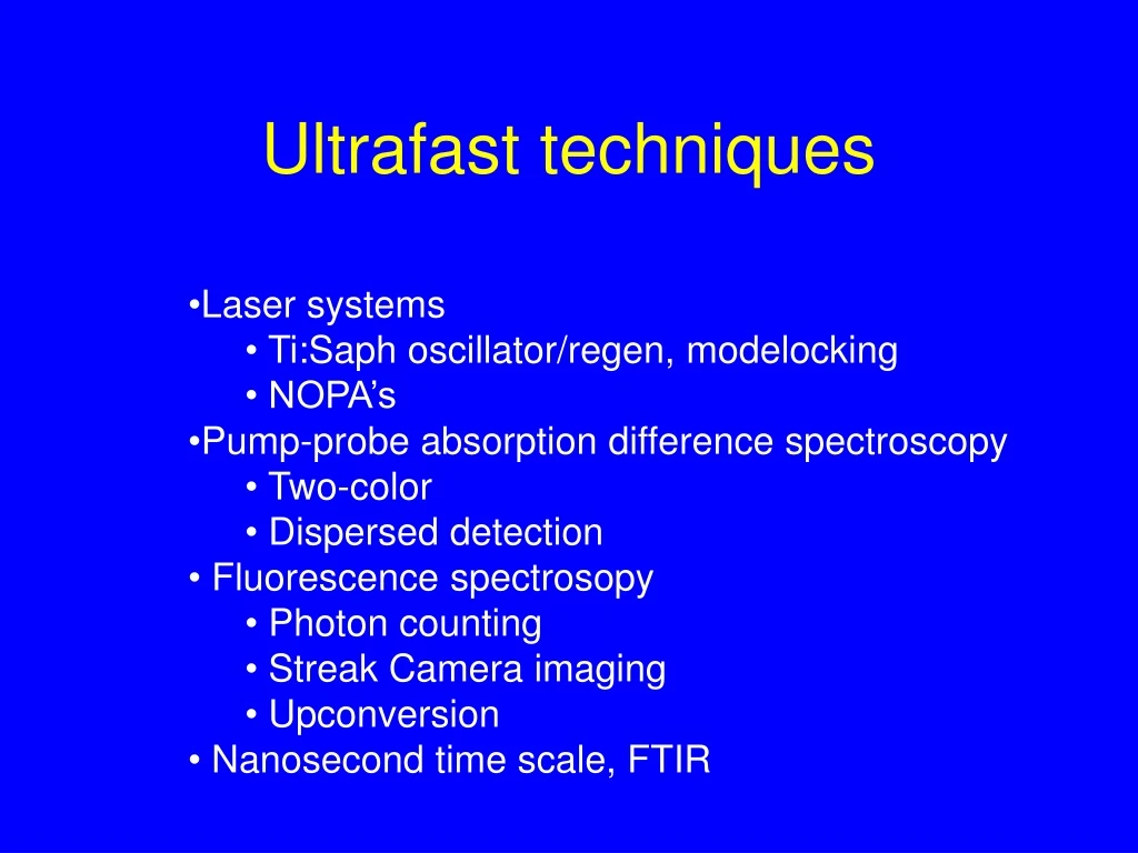
Ultrafast techniques • Laser systems • Ti:Saph oscillator/regen, modelocking • NOPA’s • Pump-probe absorption difference spectroscopy • Two-color • Dispersed detection • Fluorescence spectrosopy • Photon counting • Streak Camera imaging • Upconversion • Nanosecond time scale, FTIR
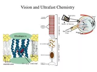
Elementary Reactions in Biology Ballistic motion on excited state potential (fs-ps) hn Diffusive motion On ground state Potential well (ms) Free Energy Reactant Product Configuration
Lasers • Light Amplification by Stimulated Emission Radiation: • Population inversion • Cavity • Gain medium -> Titanium:sapphire • Single mode, CW laser • Many modes with phase relation leads to a pulse in the cavity
Cavity Pump laser Leaky mirror For Ti:sapphire oscillatorsλ = 800 nm, Rep. rate = 80 MHz Low power ~10 nJ Pulses can be as short as ~10 fs
Amplify from nanoJ to milliJoules -> peak power 20 fs pulse if focussed to 100 micrometer = 1012W/cm-2=1000 times damage treshold most materials!
White light generationby Self Phase Modulation n(I) = n0 + n2I + …. The electrical laser field is E(x,t) = E(t)cos(ωt-kx) φ = ωt-kx = ωt – ωnx/c = ω(t-n0z/c) – n2 ωz/cI(t) ω = dφ/dt = ω – A dI/dt
Parametric generation or amplification The splitting of one photon in two: ωpump = ωsignal + ωidler Conservation of momentum: kpump = ksignal +kidler This can be done in nonlinear, birefringent crystals were the index of refraction depends on the polarization ω1 ω1+ω2 ω2
Noncollinear optical parametric amplification • When using a non-collinear phase matching angle in BBO pumped at 400 nm, the phase matching angle becomes independent of wavelength over a large part of the spectrum, for an angle of a 3.7o between pump and signal (Gale,Hache 1994) large bandwidth • The spatial walk-off (from the extraordinary pump beam) is 4.0o, with Pp farther from optical axis than kp. This is coincidently close to the noncollinear angle a! high gain • Sub-10 fs with μJ energies can be obtained (efficiency 10-30%)
optic axis idler angle signal angle ks ki α kp Optimize bandwidth by matching the signal and idler group velocities (=degeneracy for collinear beams): VS = VI cosΩ Expressed in terms of α and θ and solved for large bandwidths, one finds α = 3.7o and θ = 32o
400 nm pump ~6.4o white light seed • Shorter pulses by • minimizing dispersion of white light (no dispersive optics) • or even lengthening pump pulse • optimal compression (small apex angle prisms or gratings) • Tune by • changing delay since white light is dispersed • phase matching angle and noncollinear angle
Amplified Ti:Sapphire Laser 0.5mJ 50 fs 1khz Oscillator-stretcher-amplifier-compressor NOPA Sapphire + 1 mm= 3 fs Optical Delay Line Moving cell + Grating Diode Array
Amplified Ti:Sapphire Laser NOPA OPA 1 mm= 3 fs Optical Delay Line Moving cell + photodiode
The instrument response function The cross- or auto correlationis given by
ES 2 Excited stateaborption ES 1 Stimulated emission Ground state
Ground State Absorption Excited State Absorption Stimulated Emission Difference Absorption Spectrum: A(t)-A(t=0) A or DA l
Important experimental aspects: • Repetition rate of laser must be slower than photocycle, or samplemust be refreshed for every shot • Excitation density must be low, only when less than 10% ofcomplexes are excited you are in a linear regime -> annihilation,saturation due to stimulated emission, orientational saturation • Population dynamics are measured under the ‘magic’ angle54.7o, at other angles orientational dynamics are measuredanisotropy = r = (ΔDOD// -ΔDOD) / (ΔOD// + 2ΔOD)
Saturation The probability to excitea complex is ~ (E.μ)2Since E2 ~ I ~ n, n(Θ) = n cos2 Θ
Time-Resolved Polarized Absorption I|| I Probe Pump Dt
Pump-probe spectroscopy is a self-heterodyned third order spectroscopy: Athird order polarization is induced P(3)(w,t) ~ Χ3EprE*puEpu This nonlinear polarization is the source of a new generated field (Maxwell equation + slowly varying envelop give) Pu Pu Pr t1 Stimulated emission Time to absorb a photon, either determined by pulse length of pump, or by the dephasing time of the optical coherence i.e. ђ/absorption bandwidth
And solve to get Here is used that Im[E*j(t)P(t)= |E(t)|2Im[P(t)/E(t)] The probe absorption is related to the out-of-phase component of the polarization Signal is quadratic in both pump and probe field: S~|Epu|2.|Epr|2 And linear rather than quadratic in the weak nonlinear polarization P absorption coefficient Heterodyne detection, observation of superposition of ‘local oscillator’ field (= probe field) and signal field: I(t) = n(ωs)c/4π |Elo(t) + Es(t)|2 = ILO(t) + IS(t) + 2 n(ωs)c/4π Re[E*LO(t).ES(t)]
Ground State Absorption A or DA Excited State Absorption l Stimulated Emission Difference Absorption Spectrum: A(t)-A(t=0)
Fluorescence techniquesI. Photon Counting Laser Spontaneous emission Instrument response~30-50 ps High sensitivity, thoughmostly used with highrep rate systems, >100 KHz start stop Time to amplitude converter Monochromator or filter photomultiplier
II. Streak Camera Fluorescence Time resolution ~3 ps Whole spectrum at once Moderate sensitivity
III Fluorescence Upconversion Laser Spontaneous emission ωlaser+ωsignal Monochromator 1 mm= 3 fs Very thin BBO crystal ~50 mm detector
‘Slow’ Absorption difference spectroscopy • Fast detector • Relatively more probe light than in a fs-ps experiment, • actinic?? Ns laserpulse ΔOD Monochromator Lamp sample Photomultiplieror photodiode
FFT 3000 2000 1000 Cm-1 Step-scan FTIR Lamp IR detector MCT