Download

1 / 45
450 likes | 629 Views
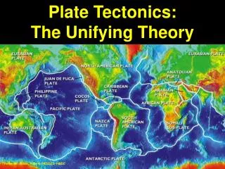
12.201/12.501 Essentials of Geophysics. Geodetic Methods Prof. Thomas Herring tah@mit.edu http://www-gpsg.mit.edu/~tah. Topics. History of geodesy Space based methods VLBI/SLR GPS (Friday). History and Types.

E N D
12.201/12.501 Essentials of Geophysics Geodetic Methods Prof. Thomas Herring tah@mit.edu http://www-gpsg.mit.edu/~tah
Topics • History of geodesy • Space based methods • VLBI/SLR • GPS (Friday). 12.201/12.501
History and Types • Geodesy: Science of measuring size and shape of the Earth (and temporal changes added in last 20 years) • Split into two fields: • Physical Geodesy: Study of Earth Potential fields (mainly gravity field) • Historically used surface gravity measurements: Boundary value problems (Greens Theorem etc): Given derivative of field on a surface, find the value of the field outside and on surface. • Space based methods for long wavelength (>300 km). Ground based tracking of satellites (LAGEOS), radar altimetry (TOPEX, JASON), satellite-to-satellite tracking (GRACE), gradiometers (GOCE), • Positional Geodesy: Determine of positions; land boundaries, maps and deformations. Lectures hear will cover latter topic. 12.201/12.501
History and Types • Although physical and positional geodesy are often treated separately, they are dependent on each other especially with development of space base geodetic methods: • When earth orbiting objects are used as measurement targets, the gravity field is needed to integrate equations of motion of object. • To use orbit perturbations to determine gravity field, the “perturbations” are measured from ground positions which need to be known at some point. • Modern methods solve these two problems simultaneously although even today this is not always done correctly. (First and second degree harmonic terms in gravity field). 12.201/12.501
Geodetic coordinate systems • Modern spaced based geodetic measurements allow determination of geometric coordinates (basically Cartesian coordinates in a global frame) • Origin of coordinates: nominally center of mass location (small movements with respect to center of figure (a few centimeters) • Orientation of axes: Z near maximum moment of inertia, X through Greenwich, Y completes systems • Mathematically compute direction of normal to ellipsoid (geodetic latitude and longitude) • However, prior to space based methods, coordinates based gravity field: • Direction of gravity vector define astronomical latitude and longitude. Height measured above an equipotential surface (geoid). 12.201/12.501
Geodetic coordinates: Latitude 12.201/12.501
Positional Geodesy Methods • Triangulation: Dates from 1600’s and the work of Snell. Uses angle measurements and 1-2 short, directly measured distance (usually ~1km). Other distances are deduced then from trigonometry. • Angles can be measured to ~1 arc sec = 5x10⁻⁶ rads. • Accuracy of this geodetic method is ~10-5 proportional error • Main geodetic method until the 1940s • Trilateration: Direct distance measurement using electromagnetic distance measurement (EDM). • Techniques developed after WW II and followed from the RADAR development. • Most methods used phase measurements at different frequencies rather than time-of-flight measurements. 12.201/12.501
Example of methods: South Africa The Meridian Arc of Abbe de LacailleMeasured in 1751 to help determine shape of Earth. 12.201/12.501
Later measurements 1840-1846 Typical sites distances are 20-50 km.Points are located on tops of mountains typicallyThe baseline measurement was in Cape Town. 12.201/12.501
1920’s triangulation network 12.201/12.501
Densification In tectonically active area, these old survey results can be used to get strain accumulation estimates with up to 150 year time spans. 12.201/12.501
Space based measurements • The advent of the Earth orbiting satellites starting in 1955, and the development of radio astronomy (Jansky, 1932) started to bring about a revolution in geodetic accuracy. • Activity started after WWII using technology developed during the war and in response to cold war. • New methods removed the need for line-of-sight Jansky 22 Mhz steerable radio telescope (1932) Modern radio telescope 12.201/12.501
Principles of new methods • Satellites allowed measurement to objects well above the surface of the earth which could be seen from locations that could not see earth other. • The electronic distance measurement methods could be used make distance measurements rather than angle measurements. (As in astronomical positioning) • Radio techniques allowed relative distance measurements using quasars • Satellite orbits perturbed by gravity field (and other non-conservative forces such as drag) and so physical and positional geodesy at the same time. 12.201/12.501
Space Geodetic Techniques • Satellite Laser Ranging (SLR): Uses pulsed laser system to measure time of flight travel from ground telescope to orbiting satellite equipped with corner cube reflectors. • First deployed in late 1960s; Lunar system deployed by Apollo and Russian programs (LLR). • Currently about 38 reporting stations (11/04). • International Laser Ranging service (ILRS): http://ilrs.gsfc.nasa.gov/ LAGEOS I: Launched 1976, 5958 km altitude, 109 deg Inclination, 411 kgLAGEOS II: Launched 1992, 5616-1950 km altitude, 52 deg Inclination, 400 km60 cm diameter spheres 12.201/12.501
Current SLR network (11/04) 12.201/12.501
Space geodetic methods • Very long baseline interferometry (VLBI): Uses radio signals from extragalatic radio sources to measure difference in arrival times at widely separated radio telescope. • First measurements in 1969: First detection on plate motion between Europe and North America in 1986. • 38 VLBI sites currently International VLBU service (IVS) http://ivscc.gsfc.nasa.gov/ Pietown Radio telescope (25 m diameter) (right) Effelsberg radio telescope in Germany (100 m diameter) (left) 12.201/12.501
Current VLBI Network (11/04) 12.201/12.501
VLBI and SLR operations • SLR sites tend to operate independently with priorities at each site as to which satellites to track. There are about 30 satellites with corner cube reflectors. SLR stations need human operators and track for 8-24 hours per day 5-7 days per week. • VLBI measurements need to be coordinated because multiple telescopes need to look at the same radio object at the same time. Sessions are scheduled for 24 hours durations with measurements every few minutes. Regular measurements programs in EOP sessions twice per week, daily intensive sessions (1-hr), plus other sessions. • There are mobile VLBI and SLR systems, but these are moved with trucks, and so tend to be repositioned infrequently. (In the 1980s mobile VLBI and SLR systems made measurements in tectonically active regions, but GPS replaced these types of measurements in the 1990s). • SLR is useful for satellite tracking, and low order gravity field changes • VLBI provides 1-day averaged station positions and inertial reference frame 12.201/12.501
Global Positioning System (GPS) 12.201/12.501
GPS Original Design • Started development in the late 1960s as NAVY/USAF project to replace Doppler positioning system • Aim: Real-time positioning to < 10 meters, capable of being used on fast moving vehicles. • Limit civilian (“non-authorized”) users to 100 meter positioning. 12.201/12.501
GPS Design • Innovations: • Use multiple satellites (originally 21, now ~28) • All satellites transmit at same frequency • Signals encoded with unique “bi-phase, quadrature code” generated by pseudo-random sequence (designated by PRN, PR number): Spread-spectrum transmission. • Dual frequency band transmission: • L1 ~1.5 GHz, L2 ~1.25 GHz 12.201/12.501
Latest Block IIR satellite(1,100 kg) 12.201/12.501
Measurements • Measurements: • Time difference between signal transmission from satellite and its arrival at ground station (called “pseudo-range”, precise to 0.1–10 m) • Carrier phase difference between transmitter and receiver (precise to a few millimeters) • Doppler shift of received signal • All measurements relative to “clocks” in ground receiver and satellites (potentially poses problems). 12.201/12.501
Positioning • For pseudo-range to be used for “point-positioning” we need: • Knowledge of errors in satellite clocks • Knowledge of positions of satellites • This information is transmitted by satellite in “broadcast ephemeris” • “Differential” positioning (DGPS) eliminates need for accurate satellite clock knowledge by differencing the satellite between GPS receivers (needs multiple ground receivers). 12.201/12.501
Satellite constellation • Since multiple satellites need to be seen at same time (four or more): • Many satellites (original 21 but now 28) • High altitude so that large portion of Earth can be seen (20,000 km altitude —MEO) 12.201/12.501
Current constellation • Relative sizes correct (inertial space view) • “Fuzzy” lines not due to orbit perturbations, but due to satellites being in 6-planes at 55o inclination. 12.201/12.501
Ground Track Paths followed by satellite along surface of Earth. 12.201/12.501
Pseudo-range accuracy • Original intent was to position using pseudo-range: Accuracy better than planned • C/A code (open to all users) 10 cm-10 meters • P(Y) code (restricted access since 1992) 5 cm-5 meters • Value depends on quality of receiver electronics and antenna environment (little dependence on code bandwidth). 12.201/12.501
GPS Antennas (for precise positioning) Nearly all antennas are patch antennas (conducting patch mounted in insulating ceramic). • Rings are called choke-rings (used to suppress multi-path) 12.201/12.501
Positioning accuracy • Best position accuracy with pseudo-range is about 20 cm (differential) and about 5 meters point positioning. Differential positioning requires communication with another receiver. Point positioning is “stand-alone” • Wide-area-augmentation systems (WAAS) and CDMA cell-phone modems are becoming common differential systems. • For Earth science applications we want better accuracy • For this we use “carrier phase” where “range” measurement noise is a few millimeters (strictly range change or range differences between sites) 12.201/12.501
Carrier phase positioning • To use carrier phase, need to make differential measurements between ground receivers. • Simultaneous measurements allow phase errors in clocks to be removed i.e. the clock phase error is the same for two ground receivers observing a satellite at the same time (interferometric measurement). • The precision of the phase measurements is a few millimeters. To take advantage of this precision, measurements at 2 frequencies L1 and L2 are needed. Access to L2 codes in restricted (anti-spoofing or AS) but techniques have been developed to allow civilian tracking of L2. These methods make civilian receivers more sensitive to radio frequency interference (RFI) • Next generation of GPS satellites (Block IIF) will have civilian codes on L2. Following generation (Block III) will have another civilian frequency (L5). 12.201/12.501
Phase positioning • Use of carrier phase measurements allows positioning with millimeter level accuracy and sub-millimeter if measurements are averaged for 24-hours. • Examples: • The International GPS Service (IGS) tracking network. Loose international collaboration that now supports several hundred, globally distributed, high accuracy GPS receivers. (http://igscb.jpl.nasa.gov) • Applications in California: Southern California integrated GPS network (SCIGN http://www.scign.org) 12.201/12.501
IGS Network Currently over 400 stations in network 12.201/12.501
IGS network • Stations in the IGS network continuously track GPS satellites and send their data to international data centers at least once per day. All data are publicly available. • A large number of stations transmit data hourly with a few minutes latency (useful in meteorological applications of GPS). • Some stations transmit high-rate data (1-second sampling) in real-time. (One system allows ±20 cm global positioning in real-time with CDMA modem connection). 12.201/12.501
Uses of IGS data • Initial aim was to provide data to allow accurate determination of the GPS satellite orbits: Since IGS started in 1994, orbit accuracy has improved from the 30 cm to now 2-3 cm • From these data, global plate motions can be observed in “real-time” (compared to geologic rates) • Sites in the IGS network are affected by earthquakes and the deformations that continue after earthquakes. The understanding of the physical processes that generate post-seismic deformation could lead to pre-seismic indicators: • Stress transfer after earthquakes that made rupture more/less likely on nearby faults • Material properties that in the laboratory show pre-seismic signals. • Meteorological applications that require near real-time results 12.201/12.501
Orbit Improvement 1993 2004 12.201/12.501
Global Plate Motions 12.201/12.501
Motions in California Red vectors relative to North America; Blue vectors relative to Pacific Motion across the plate boundary is ~50 mm/yr. In 100-years this is 5 meters of motion which is released in large earthquakes 12.201/12.501
Hector Mine co-seismic Brown dots are small earthquakes Green lines are faults 12.201/12.501
Post-seismic Estimates As more earthquakes are seen with GPS, deformations after earthquakes are clearer Here we show log dependence to the behavior. 12.201/12.501
WIDC (74 km from epicenter)Coseismic offset removed N 51.5±0.8 mmE 15.7±0.6 mmU 4.3±1.8 mm Log amplitude N 4.5 ± 0.3 mmE 0.7 ± 0.2 mmU 3.3 ± 0.7 mm 12.201/12.501
Deformation in the Los Angeles Basin Measurements of this type tell us how rapidly strain is accumulating Strain will be released in earthquakes (often large) 12.201/12.501
Repeating slow earthquakes in Pacific North West Example of repeating “slow” earthquakes (no rapid rupture) These events give insights into material properties and nature of time dependence of deformation 12.201/12.501
GPS Measured propagating seismic waves Data from 2002 Denali earthquake 12.201/12.501
CONCLUSIONS • GPS, used with millimeter precision, is revealing the complex nature and temporal spectrum of deformations in the Earth. • Programs such as Earthscope plan to exploit this technology to gain a better understanding about why earthquakes and volcanic eruptions occur. • GPS is probably the most successful dual-use (civilian and military) system developed by the US • In addition to the scientific applications, many commercial applications are also being developed. 12.201/12.501