Download
1 / 25
270 likes | 708 Views
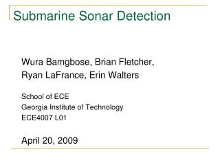
Submarine Sonar Detection. Wura Bamgbose, Brian Fletcher, Ryan LaFrance, Erin Walters School of ECE Georgia Institute of Technology ECE4007 L01 April 20, 2009. Project Overview. Sonar detection system Marine Robotics Group Navy competition. Navy Competition 2009. Bridge.

E N D
Submarine Sonar Detection Wura Bamgbose, Brian Fletcher, Ryan LaFrance, Erin Walters School of ECE Georgia Institute of Technology ECE4007 L01 April 20, 2009
Project Overview • Sonar detection system • Marine Robotics Group • Navy competition
Navy Competition 2009 Bridge Rooftop Rooftop Practice Side Competition Side Launch Platform
Technical Objectives • Amplify and detect a ping between 20-30 kHz • Determine the direction of origin of the ping • Communicate time delay with submarine’s main control system
Detect Ping Frequency: 20-30kHz 2s 1.3ms
Measure Time Delay Pinger t2 t1 t1<t2
Adjust Direction Pinger t2 t1 t1 = t2
Physical Constraints Pic of BOX & mcu 6” 5.5”
Sonar System Block Diagram Variable Gain Amplifier MCU Hydrophones ADC RS232 Pinger Measure Time Delay
Amplifiers Variable Gain Amplifier MCU Hydrophones ADC RS232 Pinger Measure Time Delay
LMC6484IN-ND Rail-to-Rail Output Swing (within 20 mV of supply rail 100 kW load) Excellent CMRR and PSRR: 82 dB Input impedance of 1 TΩ Quad operational amplifier
Amplifier Design Performance • Target gain of 100dB • Three stage amplifier circuit • Low gain first stage to limit noise of the signal • Actual gain of 84dB
Amplifier Schematic High-pass filter Low-pass filter Digital potentiometer
Band-pass Filter Target -3dB frequencies of 18kHz & 42kHz Actual -3dB frequencies of 18kHz & 52kHz
Microcontroller MCU Variable Gain Amplifier Hydrophones ADC RS232 Pinger Measure Time Delay
Sonar System Controller Samples at 1 Msps Determines time delay in samples MCU ADC RS232 Measure Time Delay
Determining Time Delay • Peak detection of signals on both channels • End detection of both signals • Cross correlation between start and end points • Cross correlation has a max at the time delay
Cross-correlation V V2
Auto-calibration t1 t2 t1 > t2 t1 = t2 Eliminates error from submarine design changes.
Demonstration Electronics Laptop Pool Serial Cable Pinger Hydrophones
Remaining Tasks Move cross-correlation code to MCU Design auto-calibration function Troubleshoot automatic gain control Test system in a pool
Overall Analysis • Done well: • Good noise filtering • High gain • Sufficient sampling rate • Improvements: • MCU with more memory • Build circuit on one PCB to improve performance and reduce size