Download
1 / 130
1.35k likes | 1.69k Views
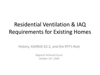
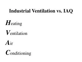
Industrial Ventilation vs. IAQ. H eating V entilation A ir C onditioning. Industrial Ventilation vs. IAQ. 24. Industrial Ventilation vs. IAQ. Industrial Ventilation vs. IAQ. Routes of Entry. Inhalation Ingestion Absorption Injection. Control Options. Process change Substitution

E N D
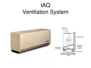
Industrial Ventilation vs. IAQ Heating Ventilation Air Conditioning
Routes of Entry • Inhalation • Ingestion • Absorption • Injection
Control Options • Process change • Substitution • Isolation • Ventilation • Administrative control • Personal protective equipment
Problem Characterization AIRFLOW EMISSION SOURCE BURTON 2-1
Burton Ex. 2-1 GROUP EXERCISE Study the figure on page 2-4 and discuss potential control measures that you might use to correct the problem. BURTON 2-4
The Atmosphere • Reaches 50 miles into space. • Pressure = 14.7 pounds per square inch.
Pressure Measurement Vacuum Atmospheric Pressure 14.7 psia
Pressure Measurement 14.7 psia = 407in. Water 14.7 psia = 29.92 in. Mercury (Hg.)
Pressure • Differences in air pressure cause movement.
Pressure Differential Causes Movement FLOW LOW HIGH FAN BURTON 3-6
Pressure Terms • Static Pressure • Velocity Pressure • Total Pressure
Static Pressure Flow SP Static pressure (SP) is exerted in all directions.
Velocity Pressure Flow SP VP Velocity Pressure (VP) is kinetic (moving pressure) resulting from air flow.
Total Pressure Flow SP VP TP Total pressure (TP) is the algebraic sum of the VP and SP.
Pressure Upstream and Downstream of the Fan TP SP VP Up-stream - - + Down-stream + + + BURTON 3-8
What is use of the term “Velocity Pressure” ? • Determine the air flow. • To design the system. • V = 4005(VP)1/2
What is use of the term “Static Pressure” ? • Accelerate the air. • Overcome resistance to friction.
Static Pressure and Velocity Pressure are Mutually Convertible When air is accelerated, the static pressure is converted to velocity pressure. = When air is decelerated, the velocity pressure can be transformed back into static pressure.
Conservation of Mass • Mass in = Mass out. • Air speeds up when the duct area is smaller. Q = VA Q = Cubic Feet Per Minute V = Velocity A = Area
YES non-hazardous gas, vapor, respirable particle uniform time emission emissions not close to people moderate climate NO toxic material large particulate emission varies widely over time large, point source emissions people in vicinity severe climate irritation or complaints Dilution Ventilation BURTON 4-1
Volume Vapor Flow Rate BURTON 4-3
Estimating Dilution Air Volume BURTON 4-5
Example 4-1 What is q, the volume flow rate of vapor formed, if 0.5 gallons of toluene are evaporated uniformly over an 8-hr. shift? What volume flow rate Qd is required for dilution to 10 ppm, if Kmixing = 2 ? (Assume STP; d = 1.0) What is the average face velocity of air in a room 10ft. * 8ft. * 40ft for these conditions? BURTON 4-6
Strategy Ex. 4-2 Step 1: Calculate the volume flow rate of the vapor emitted q. q = (387 * lbs. evaporated)/ (MW * t * d) Note:lbs. Evaporated = gal. * 8.31 * SG Step 2. Calculate the dilution air volume flow rate Qd. Qd = q * 106 * K mixing Ca (ppm) Step 3: Calculate the face velocity. V face = Qd/A Step 4: Calculate the air changes/ hour. N = (Qd * 60)/Vr
Purge and Buildup • Purge and buildup - predict contaminant buildup or purge rate. • Steady state -equilibrium maintained. BURTON 4-9
Example 4-5 An automobile garage was severely contaminated with carbon monoxide. How long will it take to purge the garage? BURTON 4-11
Chapter 11 - Makeup Air Balance • Exhausted air must be replaced. • Negative pressure without makeup air. BURTON 11-1
Make up Air • Fresh air supplied into the breathing zone of the associate.
Changes in static pressure involving radial (squirrel cage) fans cause a small change in the volumetric flow rate. Changes in static pressure involving axial (propeller) fans cause a large change in the volumetric flow rate. Overcoming Negative Static Pressure BURTON 11-2
Good Makeup Air INDUSTRIAL VENTILATION 2-4
Bad Makeup Air INDUSTRIAL VENTILATION 2-4
Reentrainment BURTON 11-9
Reentrainment BURTON 11-9
Avoiding Reentrainment10-50-3000 RULE BURTON 14-5
Recirculation of Exhaust Air • Good for non-toxic particulate control. • Can recover 40-60% of heat energy. BURTON 12-1
Types of Ventilation Systems BURTON 5-1
Why Choose Local Ventilation? • No other controls • Containment • Employee in vicinity • Emissions vary with time • Sources large and few • Fixed source • Codes BURTON 5-2
Exercise 5-3 Form your group and try exercise 5-3. Compare the operation to the parameters listed below: • No other controls available • Hazardous contaminant • Employee in immediate vicinity • Emissions vary with time • Emission sources large and few • Fixed emission source • Codes & standards BURTON 5-3
Components of a Local Exhaust System BURTON 5-4