CAD Issues & Algorithms(2)
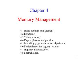
CAD Issues & Algorithms(2). 3. Synthesis 1) High-Level Synthesis. Synthesis Path. 주어진 behavior (algorithmic) 기술을 structural 기술로 변환하는 과정 . 동기 빠른 디자인 싸이클 적은 에러 넓은 디자인 스페이스의 효율적 탐색. Behavioral Specification. High-Level Synthesis. RTL Description. Logic Synthesis.

CAD Issues & Algorithms(2)
E N D
Presentation Transcript
3. Synthesis1) High-Level Synthesis Synthesis Path • 주어진 behavior (algorithmic) 기술을 structural 기술로 변환하는 과정. • 동기 • 빠른 디자인 싸이클 • 적은 에러 • 넓은 디자인 스페이스의 효율적 탐색 Behavioral Specification High-Level Synthesis RTL Description Logic Synthesis Layout Synthesis Layout
PLA Latch a b c N = a(b+c) O = (b+c)(c+d) d High-Level Synthesis Behavioral Specification in HDL + + a b c d X X CDFG + N O + X Scheduling Allocation X Assignment (Binding) O N c b d a Data-path Controller + X Controller Data-path
Scheduling • CDFG에 연산간의 의존성만이 주어졌을 때 각 연산의 정확한 시작 시간을 정하는 작업. • 결과로 생성되는 시스템 내의 연산간의 동시 수행성(concurrency)을 결정하여 성능을 결정하게 된다. • 다양한 알고리즘이 존재한다. i) ASAP (As Soon As Possible), ALAP (As Late As Possible) ii) Integer Linear Programming (ILP)- based scheduling iii) List scheduling iv) Force-directed scheduling, etc.
ASAP i) 연산의 의존성 만을 고려하여 수행 가능한 최초의 시간에 연산을 시작하게 한다. • ILP-based scheduling i) 스케쥴링 문제를 ILP로 모델링하여 최적의 해를 구하는 방법 • List scheduling i) 수행시간과 하드웨어 자원의 제약이 있는 경우 각 연산의 중요도를 계산하여 중요한 연산부터 먼저 스케쥴링 한다. ii) 중요도 계산에 따라 여러 방식이 있다. • Force-directed scheduling i) 동종의 연산이 같은 시간에 수행되는 경우를 줄여 하드웨어의 공유를 극대화함으로써 하드웨어를 최소화하려는 스케쥴링
ASAP Force-directed scheduling X X X + X X + + X X X + X + X + + + ALAP X X Distribution graph of multiply DG of add 0 1 2 3 X X 0 1 2 3 1 1 2 2 + X + 3 3 4 4 + + Data-path
Assignment (Binding) • 연산과 하드웨어 자원과의 매핑을 결정하는 과정 • 자원의 공유를 고려한다. i) 하나의 자원이 두개이상의 연산에 매핑될 때 자원이 공유된다. • 알고리즘 i) 각 자원의 종류에 따라 각각 compatibility graph(or conflict graph)를 만들고 clique partition(or vertex coloring) 문제를 풀면 된다. ii) Maximal clique안의 연산(같은 색의 연산)은 하나의 자원을 공유할 수 있다.
1 2 10 X X + TIME 1 3 6 11 X X < TIME 2 4 7 8 _ X X TIME 3 5 9 _ + TIME 4 9 3 1 8 4 10 {4, 5, 10, 11} {9} {1, 3, 7} {2, 6, 8} 7 6 2 5 11 Compatibility graph of multiply Compatibility graph of ALU
F = A and B A B F 2) Logic Synthesis • 문제정의 • 주어진 functional spec.을 만족하는 회로를 만들어 내는 것 • 문제종류 • Combinational logic optimization • Two-level minimization (PLA) • Multi-level minimization • Sequential logic optimization • State assignment • Retiming
Two-level optimization • 목적 i) Logic 을 sum-of-product 형태로 표현할 때에 product term을 최소화 하는 구현을 찾음 • 배경 i) PLA 크기 = (입, 출력의 개수) * (product term의 개수) ii) 입, 출력은 functional spec에 의해 고정 된 것이므로 크기는 product term을 줄임으로써만 줄일 수 있다. • 방법 i) Karnaugh Map ii) Quine-McCluskey Method iii) MINI, PRESTO, ESPRESSO
X1 X2 00 01 11 10 X3 X4 00 01 11 10 1 0 0 1 • Quine-McCluskey Method: Unrealistic for large problem size 2nd Reduction 0 1 0 1 8,9,10,11 10–– B 0 1 1 1 10,11,14,15 1–1– A 0 0 1 1 1st Reduction Prime Implicant Table Decimal Binary 0,8 –000 E 0 0000 0 5 7 8 9 10 11 14 15 8,9 100– 8 1000 A X X X X 8,10 10–0 5 0101 B X X X X 5,7 01–1 D 9 1001 C X X 9,11 10–1 10 1010 10,11 101– 7 0111 D X X 10,14 1–10 11 1011 E X X 7,15 –111 C 14 1110 11,15 1–11 15 1111 F = A + B + D + E 14,15 111–
Heuristic 2-level logic minimization method • 기본 배경 i) Quine-McCluskey 방법을 일부 minterm에만 적용하여 search space가 기하급수적으로 늘어나는 것을 막는다. • 방법 i) Iterative approach • Q-M 방법을 한 cube에 적용시켜 확장된 cube에 의해 cover 되는 cube들을 없애고 이를 반복 • MINI1, PRESTO2에서 사용 ii) Use unate recursive paradigm (divide-and-conquer) • Shannon expansion을 이용, 문제를 줄여 나감(until cofactors are unate) • ESPRESSO에서 사용 • S.J. Hong, R.G. Cain and D.L Ostapko, “MINI: A heuristic approach for ogic minimization,” • I.B.M. J. of Res. and Dev. Vol 18, pp443-458, Sep 1974 • 2) D.W. Brown, “A State-Machine Synthesizer-SMS,” Proc. 18th DAC pp 301-304, Nashville, June 1981
Shannon Expansion • Shannon expansion of G is defined by G=XiGxi + Xi’Gx’i where Gxi and Gx’i are cofactors of G w.r.t. variable xi. Gxi = G(xi=1) and Gx’i = G(xi=0). Ex. F=abc’+a’c+b Applying F=a*f(a=1)+a’*f(a=0), F=a(bc’+b)+a’(c+b) • The variable for recursive SE is selected to bring the cofactors as close to unate as possible. A good strategy is to use the most binate variable, i.e., variable appearing most often in its positive and negative form. • Function f is positive/negative in xi if xi appears only in uncompl/complemented form in the sum of producr form of f. • If f is either +ve or –ve in xi, f is unate in xi. If f is unate in each of its variables, f is called unate. Ex. F=ab’+cb’ is unate
Multi-level logic optimization( Random Logic 구현) • 목적 i) Function을 factored form으로 표현할 때에 literal 숫자가 최소가 되도록 한다. • 배경 i) Boolean 식으로 표현할 경우 Function 들간에 공통으로 쓰이는 sub-expression 들이 있다. ii) 이러한 sub-expression을 따로 계산하여 그 결과를 이용하면 전체적으로 면적을 줄일 수 있다. • 방법 i) Algebraic model 을 이용(weak division) ii) Boolean model 을 이용(strong division)
x=ace+bce+de+g ab(a`+b)+a`c(a`+b) =ab+a`c • 예제 x=a’+b y=abx+a’cx t=ac+bc+d x=te+g x=a’+b y=ax+a’c s=a+b t=sc+d x=te+g Boolean model Algebraic model
Sequential logic optimization: state-based model • 목적 i) State diagram으로 표현된 spec.을 주어진 목적에 맞게 최적화 하여 구현하는 것 • 종류 i) State minimization • Symbol로 표현된 state중 동작상 같은 state들을 찾아 합병하여 주는 것 ii) State encoding(State assignment) • Symbol로 표현된 state들을 digital circuit으로 구현하기 위해 bit vector로 encoding하는 것
0/0 0/0 0/1 0/1 3 1 1/1 4 3 1 1/1 4 1/1 1/1 0/1 0/1 0/0 0/0 1/0 1/1 1/0 1/1 0/1 0/1 1/1 1/1 2 5 2 5 • 예제 5 states 4 states
Sequential logic optimization: network model • 목적 i) Time-labeled variable로 표현된 spec.을 주어진 목적에 맞게 최적화 하여 구현하는 것 • 배경 i) Stream data를 처리하는 filter 등과 같은 system은 종종 time-labeled variable 을 이용한 equation으로 표현된다. • 기능: Retiming i) Delay block의 위치를 바꿈으로써 면적 및 cycle time을 최소화 함
Propagation delay • 예제(Correlator) d(P,Q) P d P 3ns Q d d d d 7ns a1 a2 a3 a4 Critical path = 24ns d d d d Critical path = 13ns a1 a2 a3 a4
Technology Independent Optimized Network Technology Mapper Network with Base Functions Network with Given Library Cell Library 3) Technology Mapping • 문제 정의 • 주어진 Boolean equation을 base function 으로 표현한 후에 역시 base function 으로 미리 만들어 놓은 cell library를 이용하여 구현하는 것 • 절차 • 방법 • Rule-based approach • Heuristic algorithms
Library Original t1=a+bc t2=d+e t3=ab+d t4=t1*t2+fg t5=t4*h+t2*t3 F=t5’ • Example t1=d+e t2=b+h t3=a*t2+c t4=t1*t3+fgh F=t4’ Optimized Network with Base function
Rule-based approach • 방법 i) 미리 정의한 rule에 의해 network의 일부를 바꿔 나감 • 특징 i) 복잡한 형태의 cell을 사용 할 수 있다. • Latch, Flip-Flops, Tri-state buffer Target Graph Replacement Graph Rules (Target graph, Replacement graph) Original one Improved one
m12 m13 gate cost input produce cover g1 g3 m1 inv 1 a g1 g1 Generate all match g5 m2 inv 1 b g2 g2 g2 • DAG covering approach m3 nand2 2 g1,g2 g3 g3 m4 nand2 2 a,b g4 g4 g6 g7 m5 nand2 2 g3,g4 g5 g5 g4 g8 m6 inv 1 g4 g6 g6 g9 m7 nand2 2 g6,c g7 g7 m8 inv 1 g7 g8 g8 m9 nand2 2 g8,d g9 g9 m10 nand3 3 g6,c,d g9 g7,g8,g9 m11 nand3 3 a,b,c g7 g4,g6,g7 Binate-covering problem m12 xor2 5 a,b g5 g1,g2,g3,g4,g5 m13 nand4 4 a,b,c,d g9 g4,g6,g7,g8,g9 m14 oai21 3 a,b,g4 g5 g1,g2,g3,g5 Covering : (m1+m12+m14)(m2+m12+m14)(m3+m12+m14)(m4+m11+m12+m13) (m5+m12+m14)(m6+m11+m12)(m7+m10+m11+m12)(m8+m10+m13)(m9+m10+m13) Valid cover: (m3’+m1)(m3’+m2)(m5’+m3)(m5’+m4)(m6’+m4)(m7’+m6)(m8’+m7) (m9’+m8)(m10’+m6)(m14+m4) Ans: m3’*m5’*m6*m7’*m8’*m9’*m10’*m12*m13*m14’
Tree-covering Approximation • Tree: 모든 node의 fan-out이 1인 DAG • Dynamic programming algorithm을 사용 i) Primary input부터 현재 node까지의 가장 좋은 mapping을 찾음 ii) 상위 node로 가서 현재까지 자료를 바탕으로 위의 작업을 반복함 Tree mapping Network with Given Library Forest of Tree DAG Network Tree Partitioning Cell Library
4. Place & Route1) Placement • Placement란? • 레이아웃 공간에서 면적이나 타이밍 조건 등을 만족하는 functional cell과 module의 위치를 결정하는 작업 • 방법 • Exhaustive search로는 solution space가 너무 크므로 알맞은 heuristic 이용 • 예) Min-cut, simulated annealing, force-directed알고리즘 등 Gate-level netlist Cell placement
Placement의 성능 기준 • 라우팅 가능성(routability) : gate-array, sea-of-gates에서 중요 • 라우팅 밀집도(congestion) : standard cell에서 중요 • 신호선 길이 : multi-layer 라우팅이 가능해지면서 라우팅 면적보다 칩의 타이밍 성능이 중요해짐 • Wire 길이의 예측 Semi-perimeter length=12 Source to sink length=19 Steiner tree length=13
Maximum cut의 최소화 • Maximum cut • 회로를 partition했을 때, 각 partition사이를 잇는 net의 최대 개수 • 이 값이 증가하면 라우팅 트랙 개수가 더 필요하게 되며, 따라서 routability가 떨어지게 됨 • Maximum cut을 줄이는 것이 Min-cut 알고리즘 • 타이밍 최적화 • Interconnect delay가 증가하게 되면서 placement의 중요도 증가 • Interconnect와 path에 대한 타이밍 제한 조건을 placement 알고리즘에 포함
Constructive approach • 부분적인 placement 조건으로부터 전체적인 placement를 만드는 방법 • 종류 • Min-cut, cluster growth, branch and bound • Iterative approach • 전체적인 대강의 placement를 하고 재배치를 해 나가면서 전체 placement를 향상시키는 방법 • 종류 • Simulated annealing, genetic 알고리즘
Min-cut placement 알고리즘 • 연결이 많은 부분을 서로 가까이에 놓는다는 개념 • 회로를 partition이 최소로 될 때까지 반복적으로 분할 c1 2,4,5,7 8,12,13,14 1,3,6,9 10,11,15,16 8 c2 14 4 2 1 7 5 12 3 2 4 8 14 9 c4a 13 6 5 7 12 13 11 16 c2 1 9 11 16 15 10 c4b 3 6 10 15 c1 c3a c3b
Simulated annealing 알고리즘 • 온도가 높아졌다가 서서히 낮아질 때, 전체의 에너지 상태가 낮아지는 현상을 이용 • 온도가 높을 때는 cost가 어느 정도 증가하는 move도 선택 • 온도가 낮아지면서 cost가 증가되는 move를 허용하지 않음 able to climb at higher temperature cost configurations global minimum local minimum
accept ( c(x’), c(x), T ) { c = c(x’) - c(x); if (c <= 0) { // c < 0 : cost 개선 return(1); } else { // c > 0 : cost 악화 y = exp( - c / T ); r = random ( 0, 1 ); if ( r < y ) { return ( 1 ); } else { ruturn ( 0 ); } } } Inner loop criterion the number of iterations should be performed at each T Generate function • start with random placement • pairwise interchange, single module movement, orientation change Simulated annealing algorithm Begin T = T0 x = x0 while ( stopping crit. is not sat.) { while ( inner loop crit. is not sat.) { y = generate(x); if (accept ( c(y), c(x), T ) ) // c(a) : cost x = y; } T = update(T); } End Updating temperature Tnew = (Told) * Told (T) 0.95 T large (T) 0.8 T small Stopping criterion stop when cost function has not been reduced at 3 consecutive temperature
PMX crossover의 예 ) Random cut point b g c f e i d h a a g h c b i d e f Parent 1 Parent 2 먼저 그대로 전달 b g c a h i d e f offspring 이 자리에 f와 e가 중복되므로 parent 2의 f와 e자리에 있는 a와 h를 전달 • Genetic 알고리즘 • 진화의 과정을 모사한 알고리즘 • 기본 operator • Crossover : 두개의 parent에서 정보를 물려 받은 offspring 생성 • Mutation : crossover에 의해 생성된 offspring에 random한 변화를 일으킴 많이 쓰이는 mechanism은 pairwise interchange • Inversion : 일정 부분의 배열을 거꾸로 바꿈 예) [bid | efgch | a] [bid | hcgfe | a]
Genetic Algorithm Np = population size, Ng = number of generations, No = number of offsprings, Pi = inversion probability, P = mutation probability Begin Construct_Population(Np); for (j = 1 to Np) Evaluate Fitness(Population[j]); for (i = 1 to Ng) { for (j = 1 to No) { (x, y) Choose_parents; offspring[j] Generate_offspring(x,y); for (k = 1 to Np) With P, Apply Mutation(Population[k]); for (k = 1 to Np) With Pi, Apply Inversion(Population[k]); Evaluate Fitness(offspring[j]); } Population Select(Population, offspring, Np) } Return highest scoring configuration in Population End
Force-directed 알고리즘 • 각 cell들의 연결 상태를 마치 스프링들이 서로 연결된 것처럼 보고 힘의 평형 상태가 되는 placement를 찾음 • 알고리즘의 예 i) 가장 큰 힘을 받는 cell을 선택 ii) 이 cell을 힘의 평형 상태에 가장 가까운 slot로 이동 iii) 원래 slot에 있던 cell을 이동한 cell의 빈자리로 옮기고 처음부터 반복 • 기타 알고리즘 • neural networks
2) Routing • Routing이란? • 레이아웃 공간에서 netlist와 일치하도록 각 port를 연결하는 작업 • Routing 순서 • Global routing • Detailed routing이 이루어지기 전에 각 wire들을 각 routing 영역에 할당 • Routing congestion이 적도록 분배 • Detailed routing • Routing 영역에 할당된 net들을 특정 트랙(track)에 할당 • 예) channel routing, switchbox routing
Routing 영역 • Macro 블록이나 cell들 사이의 공간 • Over-the-cell routing의 경우는 예외 • 세 가지 형태로 분류 • Channel, switch-boxes, L-shaped regions • 각 영역이 결정되면 영역들을 어떠한 순서로 routing을 할 것인지 결정 macro block macro block L-shaped region channel channel switch box channel
a b c track a c b • Channel routing • 아무런 obstacle이 없고 위와 아래에 terminal의 위치가 정해져 있는 직사각형의 영역을 가정 • 효율적이고 구현이 간단 • 수직한 wire 부분과 평행한 wire 부분에 서로 다른 layer를 할당 • 예) Left-edge 알고리즘, greedy channel router
Maze router • Grid model 이용 • 모든 routing 영역을 정사각형의 grid cell 배열로 표현 • 모든 port들과 wire, cell들의 bounding box들도 grid에 맞춰 정렬 • Obstacle이 존재해도 routing 가능 8 7 6 source t t 8 7 6 5 7 8 4 7 6 2 1 2 3 s 6 5 4 s 1 2 5 4 3 2 1 2 4 source selected path
Routing Issues in Deep Sub-Micron • Cross-Coupling 효과 • 공정이 줄어들면서 선폭도 따라서 감소하였지만, 선의 높이는 저항을 줄이기 위해서 거의 변하지 않음 (metal line aspect ratio = 1.4 : 1 at 0.25um) Vertical capacitance(Cv)보다 horizontal capacitance(Ch)가 dominant해짐 At 0.25 um process
Cross-coupling을 실험하기 위한 wire의 RC 모델 • 실험하고자 하는 wire의 양옆에 평행하게 지나가는 bus net이 있을 경우를 모델링 • 가운데의 victim wire가 horizontal capacitance에 의해서 양 옆 wire에 연결 RC model for cross-couple effect
서로 다른 방향으로 transition • 이웃하는 선의 transition에 따라서 delay가 변화 • 오른쪽 그래프에서 보는 바와 같이 delay가 53% ~ 143%까지 변화 • Cross-coupling factor로 모델링 • 이웃선과 다른 방향 : fcc = 2 Cheff = fcc * Ch = 2 Ch • 이웃선 transition 없음 : fcc = 1 Cheff = fcc * Ch = Ch • 이웃선과 같은 방향 : fcc = 0 Cheff = fcc * Ch = 0 Cwire = Cheff + Cv 로 모델링 할 수 있음 이웃선의 transition 없음 서로 같은 방향으로 transition Cross-coupling effect vs. interconnect length • 해결 방법 • 선 사이의 간격을 늘임 • 서로 다른 방향으로 transition 하는 선들이 따로 배열되도록 bus line을 할당 • power line으로 shielding
Clock distribution • Clock rate의 증가와 wire delay의 증가로 인하여 clock network의 디자인의 중요해짐 • Clock skew를 줄이기 위하여 level수, level 당 driver 개수, wire의 길이, 선폭, 간격, shielding 등을 조정 Clock shielding
Driver 크기 증가 한 개의 driver 중간에 Repeater 삽입 • Repeater insertion • Buffer의 크기 조정만으로 timing constraint를 맞추기 힘든 긴 net에 대해서 repeater를 삽입 • Driver 크기가 일정 이상 커지면 그 증가폭에 비해 성능이 좋아지지 않음 • 오른쪽 그림에서 보는 바와 같이 4000m 이상일 경우에는 가장 큰 driver를 쓰는 것 보다 중간에 작은 크기의 repeater를 삽입하는 것이 더 유리
Global power bus power refresh Standard cell block • Power line의 IR-drop • 선폭이 줄어듦으로 해서 저항이 증가하고, clock rate가 증가함으로 해서 전류량이 증가 • Power를 많이 소모하는 칩의 경우 0.5 V 정도의 voltage drop이 발생하여 칩의 오동작을 일으킬 소지가 생김 • Power network의 가이드라인 • Power bus들을 계층적으로 설계 : global power bus와 하위 level의 power bus • 전체 칩의 peak power가 나오면 이에 따라 각 power line의 width를 조절 • Standard cell block 내에 power refresh를 삽입